PLEASE NOTE: If you had an account with the previous forum, it has been ported to the new Genetry website!
You will need to reset the password to access the new forum. Click Log In → Forgot Password → enter your username or forum email address → click Email Reset Link.
11 hours ago, Sid Genetry Solar said:As long as the generator's Neutral line is kept separate from any ground-neutral bonding systems--check for a potential backfeed condition if more than 2 wires come from the generator. I know, I don't like it either--but I unfortunately didn't realize the issue until after the design had been manufactured.
https://www.ecmweb.com/content/article/20892808/the-key-to-making-proper-neutraltocase-connections
is this what you are talking about?
That almost sounds like whats going on with my master, hmmmm. cause even witht he gs off it still does the same thing, do I just remove the N from input and leave the l1 maybe?
No, your system setup is at 120v, so this issue does not apply. I suspect there's an external wiring mistake; need to get with you and figure that out.
29 minutes ago, JNock said:https://www.ecmweb.com/content/article/20892808/the-key-to-making-proper-neutraltocase-connections
is this what you are talking about?
No. The current revision GS control boards were designed for only 2 AC input wires--either single phase 120 (L1 / N) or single phase 240 (L1 / L2), with the center tap for 240v generated by the inverter transformer. As such, the control board was designed to only disconnect L1...because disconnecting 1 of 2 wires stops the power flow. L2 input is directly wired to the same post as L2 output.
The issue is that if a split-phase input is wired to the inverter, with L1 / L2 going to the "input" terminals, and "N" going to the output Neutral (via direct connection, shared Neutral post and/or ground-neutral bonding)...the transformer gets AC input power backfed through the L2 / N circuit, even though the L1 relay is open. The inverter now has 3 input power wires...and it's only capable of disconnecting 1. This condition will pretty well blow the inverter out.
For a generator, you can simply avoid using the Neutral output terminal, and--presuming the generator chassis isn't shorted to it's Neutral terminal--and the generator chassis isn't bonded to a panel Neutral that's connected to the inverter (basically an implicit direct wire between the generator neutral and inverter neutral)...you'll be just fine.
I listed the test instructions for that above:
<iframe allowfullscreen="" data-embedauthorid="2" data-embedcontent="" data-embedid="embed2488262503" scrolling="no" style="height:295px;max-width:500px;" data-embed-src="/topic/175-charging-disabled/?do=embed&comment=3019&embedComment=3019&embedDo=findComment">
Like I mentioned, this issue is fixed in Rev. C boards, but those are currently in the prototype stage, not production.
7 minutes ago, Sid Genetry Solar said:No. The current revision GS control boards were designed for only 2 AC input wires--either single phase 120 (L1 / N) or single phase 240 (L1 / L2), with the center tap for 240v generated by the inverter transformer. As such, the control board was designed to only disconnect L1...because disconnecting 1 of 2 wires stops the power flow. L2 input is directly wired to the same post as L2 output.
The issue is that if a split-phase input is wired to the inverter, with L1 / L2 going to the "input" terminals, and "N" going to the output Neutral (via direct connection, shared Neutral post and/or ground-neutral bonding)...the transformer gets AC input power backfed through the L2 / N circuit, even though the L1 relay is open. The inverter now has 3 input power wires...and it's only capable of disconnecting 1. This condition will pretty well blow the inverter out.
For a generator, you can simply avoid using the Neutral output terminal, and--presuming the generator chassis isn't shorted to it's Neutral terminal--and the generator chassis isn't bonded to a panel Neutral that's connected to the inverter (basically an implicit direct wire between the generator neutral and inverter neutral)...you'll be just fine.
I listed the test instructions for that above:
<iframe allowfullscreen="" data-embedauthorid="2" data-embedcontent="" data-embedid="embed5352168395" scrolling="no" style="height:294px;max-width:502px;" data-embed-src="/topic/175-charging-disabled/?do=embed&comment=3019&embedComment=3019&embedDo=findComment">
Like I mentioned, this issue is fixed in Rev. C boards, but those are currently in the prototype stage, not production.
I just tried hooking l1 and l2 from the grid , tested for power on the output block for back feed and there was none, turned on the inverter and it beeped angrily at me saying something like invalid ac input (where it’s positioned upside down it’s hard to read). So I have absolutely no way to use this thing as a battery charger right now which is literally 50% of the reason why I need it. Sean does not handle the phone well, he would not answer at all last week. I’d rather just have the unit accept a 120v input and I’ll just plug it into the generator outlet or the grid for battery charging.
I just tried hooking l1 and l2 from the grid , tested for power on the output block for back feed and there was none, turned on the inverter and it beeped angrily at me saying something like invalid ac input (where it’s positioned upside down it’s hard to read). So I have absolutely no way to use this thing as a battery charger right now which is literally 50% of the reason why I need it. Sean does not handle the phone well, he would not answer at all last week. I’d rather just have the unit accept a 120v input and I’ll just plug it into the generator outlet or the grid for battery charging.
Pretty sure I know why...it's probably registering 270vAC or something on the input due to nonlinearity on the AC feedback circuit (my design fault again...will be fixed on the next board revisions.) You can correct this from CFG -> System -> Calibrate Readings -> AC Input line, adjust the calibration number (until the feedback reads what you measure on the AC input with your meter). Depending on the charge settings (which you should check/set before trying this!), it may switch directly into charge mode, etc.
Personally, I'd set the System Mode to Inverter Only (CFG -> System -> Mode = "Inverter Only", not "Normal") to prevent it from switching to grid, until the AC input calibration is corrected. Then after double-checking the charge settings, set the System Mode back to Normal, and it should switch over if so configured (ATS / UPS, charge threshold triggers, voltage setpoints, etc.)
Working on the manual now...hopefully will be able to get it out before too long.
where it’s positioned upside down it’s hard to read
Sorry, I'm behind the game with the manual. You can flip the LCD screen (and buttons!) from the settings. CFG -> Appearance -> UpsideDn -> set to Yes. (It'll garble the screen up pretty badly--not sure why yet--but if you exit the menus, it'll redraw and correct.) Note that this will also flip the button functionalities as well (swapping Up and Enter).
Personally, I'd set the System Mode to Inverter Only (CFG -> System -> Mode = "Inverter Only", not "Normal") to prevent it from switching to grid, until the AC input calibration is corrected. Then after double-checking the charge settings, set the System Mode back to Normal, and it should switch over if so configured (ATS / UPS, charge threshold triggers, voltage setpoints, etc.)
I’ve tried everything you said and it simply doesn’t work
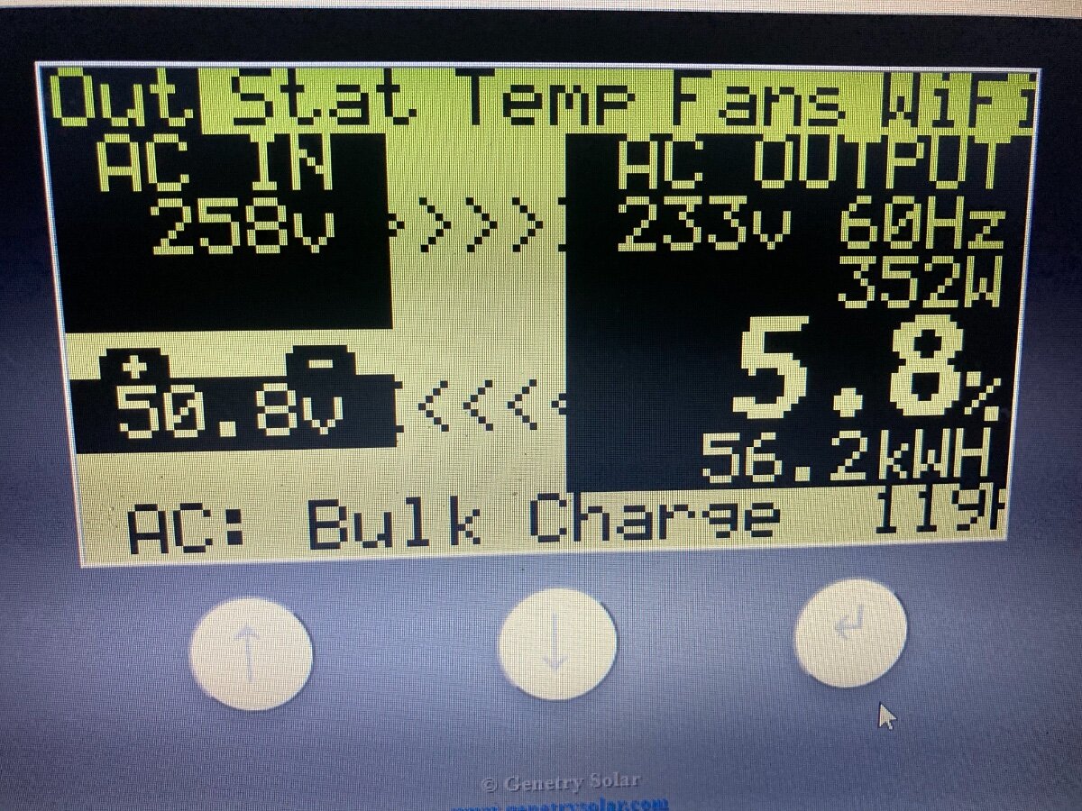
What's the registered AC input voltage on the main page?
It’s 247v on the meter and I can only select a calibration of 226 or 270 something
2 minutes ago, Sid Genetry Solar said:What's the registered AC input voltage on the main page?
Originally it said like 350 or something until i changed it
Originally it said like 350 or something until i changed it
Sounds like I need to run a video call with you to figure out what's going on. I've had firmware tweaks/issues with it reading double the AC input voltage that it should on Rev. B boards, thought I had that fixed (noting that you're on Rev. 1.1r3). Definitely need to look into this a bit closer.
1 hour ago, Sid Genetry Solar said:Will do that as soon as I can. Another meeting here now...hopefully by 4 PM?
That’s fine yes
I had a really enlightening and productive conversation with SID about my issues and we have solved all of them. What a intelligent and awesome guy! I love this inverter.
I would recommend removal of the phone number from all posts if possible now that everything is sorted.