PLEASE NOTE: If you had an account with the previous forum, it has been ported to the new Genetry website!
You will need to reset the password to access the new forum. Click Log In → Forgot Password → enter your username or forum email address → click Email Reset Link.
FWIW, in the industrial world, we use active cooling so that equipment doesn't have to withstand such conditions.
More practical to control the environment than engineer devices for such an environment.
No need to over-complicate matters. 🙂
"Oh, let's make a 12kw inverter, it's just double the size of a 6kw." Whew, was that an understatement!
You are not done yet as the parts require higher spec and difficult to get . Making any 12 kw inverter to run continuously at 120 degree F is not possible with only air cooling as the parts will require military spec and no way to sell the GS 12 kw for under 3000 dollars but more like 12000 dollars or more .
Something I found when dealing with blown horizontal output transistors in CRT display systems was the spike that occurs from the transistor switching off could anly be handled by adding a small cap across the primary coil to dull the spike, than a diode to shunt it
The FETs have the diodes in them but the cap catches the rising edge
Something I found when dealing with blown horizontal output transistors in CRT display systems was the spike that occurs from the transistor switching off could anly be handled by adding a small cap across the primary coil to dull the spike, than a diode to shunt it
My guess here is that the slew rate of the spike was too fast for the diode. Diodes have a switching delay--and during that time a spike will not be "clamped." If the slew rate is fast enough, it can reach a damaging level BEFORE the diode clamps it. I haven't been able to find clear "forward switching delay" specs (or many specs at all!) for a 1N4007, but I am aware of the "reverse recovery time" specification. (Assuming that the switching time will be similar??)
For example, it appears that the "reverse recovery time" of a standard silicon 1N4007 is closer to 2uS--which when a slew rate is measured in v/ns (volts per nanosecond) that's an eternity!
High speed switching circuits generally utilize "ultra fast recovery" diodes, which can have a recovery time as low as ~35nS (= 0.035uS), depending on the voltage and specification.
...so this is where the capacitor comes in handy, sized to "snub" the spike from exceeding unsafe potentials until the diode can react. At least that's my theory 😉.
Your theory is correct
The diode switching delay allows un snubbed spikes from the coil
A cap across the coil has no switching delay allowing it to effectively snub the spike
When coil current is cut the coil dumps it's stored energy by running the voltage up and is pretty much instant
The size of the spike depends on how much power the coil was absorbing at the time
The spike should be considered as J not V as it's a set amount of energy but the voltage or current could be anything
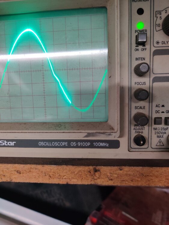
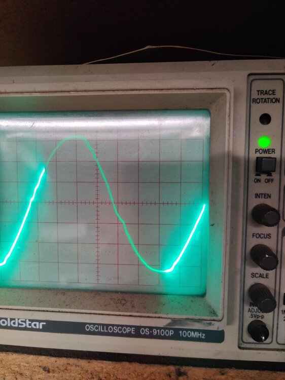
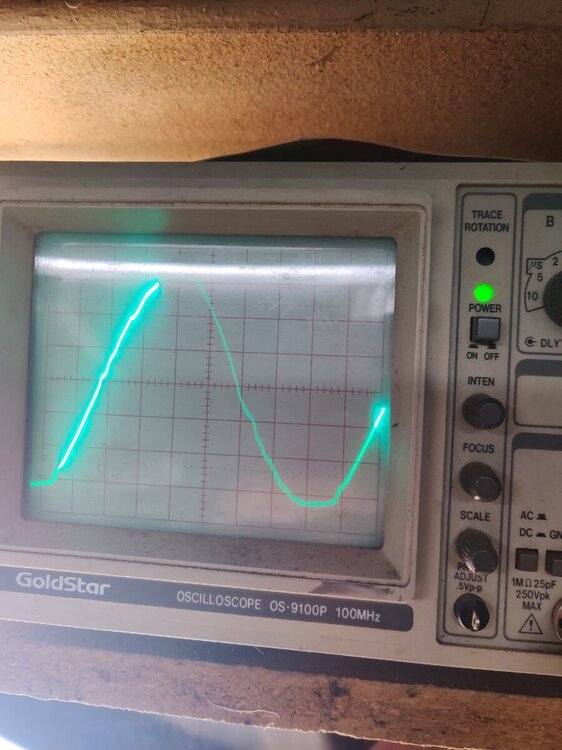
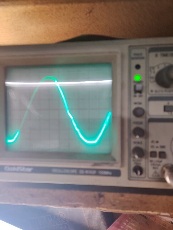
Much cleaner sign wave with cap across primary and it should completely eliminate spike damaged FETs
Running the shop light (E ballast) the input watts go up 2W 80W to 82W but running a small AC motor the input watts went down 2W 92W to 90W with .22uf across the primary wires on the transformer
Pardon me, but I am failing to see any significant difference between the 2 pictures....
Worth noting that all of the MOS boards have a 0.1uF + 220R snubber circuit across them (C1 + R3). That resistor gets pretty hot...needs to be physically bigger!
In theory, of course, the "perfect" place for a snubber cap would be after the ferrite chokes on the transformer primary...but I calculated a buck-converter equivalent of somewhere north of 100uF @ 50vAC (48v), a bit difficult 😉
Funny that we used to have a 20MHz GoldStar. Biggest complaint with it was a bad connection in one of the front panel switches causing it to have a random left-direction offset, but other than that, it was pretty good. (Add a rubber band between the offending knob and a different one to "hold the screen.") Nowadays I've got what some people call a "Nintendoscope", a DSO (Siglent SDS1104X), and I have no regrets. SO handy to be able to hit the "Stop" button and then examine what I'm looking at...
Without the cap there is a knee in the wave shortly after the peak
It's much reduced by the cap
I'm suspecting the core temp on the transformer could be reduced at higher loads by smoothing out the chops from the wave slicer (less effective resistance without the chop frequency)
The snub cap needs to be very low resistance from the coil
Having a resistor in line with the cap just let's the initial spike run up
You don't need the cap sized for 60Hz you need it for about 48Khz
Add a decay slope to the chop wave
You aren't using the transformer for the wave shaping only voltage shifting
So filter the wave before the transformer and you protect the FETs from spikes and the transformer from higher frequency heating
Just did some playing
0.22uf across the primary works well
Increasing it just increases idle
Removed 1 of the 4.7uf filter caps
Output noise didn't really change much
Tried adding the cap 4.7 back on to the other phase and current and noise went up not down
Now removing both caps and putting 1 smaller one line to line seems likely the best option
Pulled the filter caps and learned the regulation is unfiltered
Had a small toroid core around here someplace...need to add it to the wire from the transformer to the controller board so I can use smaller cap without making the regulation chatter
Pulled the filter caps and learned the regulation is unfiltered
It's a PJ...the regulation is ALWAYS oscillating. But if it's going into an even bigger oscillation, that kinda tells you that the output AC wave isn't very clean.
Output noise didn't really change much
Something else you can try is grab a older AM radio and listen to the white noise, I can hear changes in the noise with different filtering that doesn't show up on the scope. May not be your thing though but I like to listen the AM radio in the boonies so I have spent time to clean up the noise on my PJ.


