PLEASE NOTE: If you had an account with the previous forum, it has been ported to the new Genetry website!
You will need to reset the password to access the new forum. Click Log In → Forgot Password → enter your username or forum email address → click Email Reset Link.
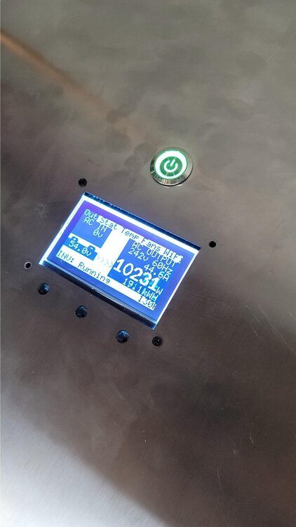
Here are some pictures of our new 12kw prototype which should be here by the end of Feb. You can note some of the new covers and connectors we have added to this unit to help with UL. We have not set a price for this unit yet but will in the coming weeks, Just like our 6kw inverters this will have all the great features such as daisy chain, 3 phase, etc. It will do 12kw with an ambient temp of not greater than 100F. Higher output is possible with a cooler ambient temp.
Edit : as Sid noted this is not the final design, we have a few bugs to iron out in the case design but this gives you a really good idea of what the final product will look like.
Tell us what you think!
-Sean
//content.invisioncic.com/g308908/monthly_2021_02/8d0627e34f20eefb11da78305e7404d.thumb.jpg.d9e2322a4c9082c8d7fdfb764b84645e.jpg
//content.invisioncic.com/g308908/monthly_2021_02/09c41f8564b81410dbbaa225dc99356.thumb.jpg.04baa3bc6589f7fa28930d56bd764e68.jpg
//content.invisioncic.com/g308908/monthly_2021_02/91c0d4c097f8def84378548a259070c.thumb.jpg.9acc895cf7d124f965432544f8a4f9fc.jpg
//content.invisioncic.com/g308908/monthly_2021_02/96308718669a11b7da6da3aeb3a1950.thumb.jpg.3a9ff7611b6ef03c69583e0039ec293b.jpg
//content.invisioncic.com/g308908/monthly_2021_02/d8343d1c7a0084e1f5aee9bd41bfe8f.thumb.jpg.5b49148d66d1dce2b9c97710157e9692.jpg
//content.invisioncic.com/g308908/monthly_2021_02/e2ec19b871f387bdd92d038b22231ba.thumb.jpg.ab7d57258e5fe4c72bd49d4733f966fc.jpg
//content.invisioncic.com/g308908/monthly_2021_02/ee8c027c7636b47ae09b33fb747df2b.thumb.jpg.8ed151b836ea5541b64312ed9af8a247.jpg
//content.invisioncic.com/g308908/monthly_2021_02/f05ac019f4e9e91ab60047fa24e1a11.thumb.jpg.baefa34dddec1126c2de6b453faef1d1.jpg
//content.invisioncic.com/g308908/monthly_2021_02/f9b190aafbf4bf18b3c95de7f1eeeb9.thumb.jpg.ca7ba3505b418f89198a61f0aab4a319.jpg
//content.invisioncic.com/g308908/monthly_2021_02/fb9f3edd585a9d11e1523e3ff83aa75.thumb.jpg.ef32753a3041675bda51760bd3976fad.jpg
Please note that there are some significant mistakes in the unit showed here...we were fortunate to get this sample unit express shipped to us before the Chinese New Year holiday. It will take some time to test the unit, get the issues worked out, and then finally ordered.
Who shrunk the control board? 🤣 Is that going to be what comes in our 6K units also? Do like those battery connectors better. I take it that the indented section is where the output wire terminals are going to be hidden behind a plate with a knockout for a conduit/sealtight connection.
Haha, I'm really having fun shrinking the control board as much as possible, limited in the Rev. B board by the screw mounting holes! That's a Rev. B GS control board (including ground bonding, 5A generator start, etc.)...and yes, it's smaller than the Rev. A.1 control board in the current shipment of inverters that we're anxiously awaiting, winter storm regardless. I don't have a Rev. B GS board on my desk yet, so I'm anxiously awaiting that too.
Yes, same control board across the line, 3K, 6K and 12K. Designed to handle at least 50A on the output side, and 75vDC on the input side, so I think it's sufficient 😉
Had to laugh when the factory boss said, "control board is a little small." They liked the battery connectors so much that you'll probably start seeing them in Power Jack inverters too...oh well...
Yes, you can see the AC cover plate in the second photo...it is on backwards, but at least it's on. 3/4 knockout size to meet UL code. Might need to enlarge the AC output box a smidge, but it contains a 5-pin 80A wire terminal block.
Battery conntor? You mean the outside or the inside, and if so if its the outside what is different about it?
Battery connector is the bolt on the inverter that you connect the battery wire to. The stock Power Jack connector is an exposed bolt with no cover; the new battery connector on the GS 12kw inverter has a plastic cover that bolts over an M10 stud. Bit safer, you won't short your batteries out by dropping a wrench across the inverter terminals.
Will there be a 6k version that I can get for mine comeing out? Don't think I'll need it since the inverter battery end will be about 6 inches under a whelf above it.
6kw inverters so far use the stock PJ terminals (single set, not doubled), though we may switch to the covered bolt design down the road.
What are the dimensions of that thing?
Dimensions of the 12kw inverter? Approximately 50cm long, 44cm wide, and 20cm tall. (~20" long, ~17.5" wide, and ~7.75" tall.) Weighs about 120lbs.
That is a beast....crazy big and heavy.
Update on the 12kw inverter: I made a custom cable using 5 lengths of 22AWG single-strand shielded wire. Sean ran it to just over 6kw today with no issues, temps peaking at around 111 Fahrenheit--not bad. With the stock PJ ribbon cable, a 6kw load would run the FETs into redline temperatures--and loads bigger than that would cause them to melt down and fail. So this is very good news. After a bit more sunshine to recharge the battery bank, we'll see what happens with a full load test.
