PLEASE NOTE: If you had an account with the previous forum, it has been ported to the new Genetry website!
You will need to reset the password to access the new forum. Click Log In → Forgot Password → enter your username or forum email address → click Email Reset Link.
We have a customer that needs 480v output from a 24v bank. Can we just use a 12-volt transformer instead of a 24? Or will the computer get mad at us?
I will be more than happy to replace the voltage sensing transformer (which I believe is a 26:1) with a 52:1 transformer, so that the processor will think we are in the correct voltage range. Do you think she'll know the difference?
- Paul
I assume you are referring to a PJ inverter control board? It will have to be a 240v-regulating inverter (i.e. they wire the transformer Neutral line directly to the front panel.) Can't be a 120v-regulating inverter (L2 directly to the front panel).
A 12v transformer on a 24v system will NOT work due to the magnetics of the transformer core. It'll saturate and blow FETs pretty much instantly--and even if it somehow doesn't blow FETs, you'll have horrible efficiency. Basically, the core can only store a certain amount of power without "saturating". Transformer winding specifications are determined by the turns-per-volt of the core (dependent on cross section, material, etc., etc.) Most smaller PJ trannies are around 0.8v/turn (you can easily measure this with a voltmeter on a running inverter: put the meter in AC scale, put one probe through the center of the "donut", and then short the 2 probes together on the other side), though their bigger ASL9 runs >1.5v/turn. Their ASL11 seems to run close to 2v/turn.
Doubling the input voltage would be attempting to force the core to double the rated voltage (i.e. 1.5v/turn -> 3v/turn), which isn't going to work very well, if at all.
What I would suggest (assuming you know someone who can wind you a transformer)...is to use a custom wound 480v transformer. Instead of having two 120v output taps for split-phase 240vAC, you'll need two 240v output taps--"split-phase 480vAC." (This will require twice the number of turns on the AC output side than a regular 240vAC split-phase transformer. You will probably need thinner wire; determine the size of the wire by the ampacity required for the specified load). And instead of connecting the L1-L2 480v output to the inverter, you will only connect one of the 240v phases to the inverter (i.e. L1-N) for regulation...no modification to the control board is necessary.
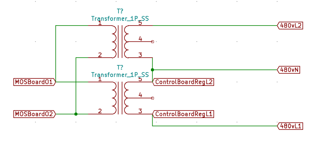
OR...redneck engineering again...you can use two matched 240v split-phase transformers on the same inverter, wiring both "low voltage sides" directly to the same MOS board. Ignore both Neutral leads on the output sides--wrap them in electrical tape or simply cut them off. One transformer's output goes to the control board regulation (like it would stock--it can even be a 120v regulating control board if you didn't cut the Neutral lead off that tranny!)...and you connect the output of the 2nd tranny in series with the first one...presto: 480vAC out. (If you get the phase reversed, it'll negate to 0v out...you'll need to swap the polarity of either side of either tranny to fix that.)
Let us know what happens... 😎🤯
Brilliant! We'll give this a try.
I am assuming there is no way to configure this with the 120 degree 3 ph boards?
Unfortunately, I just found out that this project is for a 3-phase motor application (I originally assumed it was for 480v induction heating, because this company builds heaters). As a last resort, I'm assuming that we can use a 240v, 3-ph PJ setup and run it through a separate pad-mounted 2:1 transformer to get the 480V we need.
We are setting this up with a 24-volt bank of submarine batteries (168 kWh total capacity), so obviously space is not an issue.
PJ does not support 3-phase, or any form of AC input sync. However, with the GS upgraded firmware in a PJ inverter, it is possible to support 3-phase with 3 separate inverter control/FET boards. One master inverter, and 2 slave inverters running 120 and 240 degrees offset from the master signal.
You would then need 6 transformers total to get the full output (2 per "leg") for 480vAC. Which of course is a lot of power ;-). Or like you said, an intermediary 3-phase step-up transformer.
Or maybe if this is a one-off project that needs to last for awhile without blowing up...you could get with Sean and maybe get some genuine GS control boards to replace the PJ control boards. We have very limited stock right now, and are waiting for the M5 screws for the AC terminals...but there's a possibility there. Such are the challenges of getting started with a completely new product...the up front costs to get all the materials, the delays to get them...! We will be in much better shape with stock by summer, I promise 😉
Sid, real Redneck engineering would be my way of doing it. Just buy a 120/240 to 240/480 Volt transformer of the right Wattage. That way I can goof off quicker. 🙂
