PLEASE NOTE: If you had an account with the previous forum, it has been ported to the new Genetry website!
You will need to reset the password to access the new forum. Click Log In → Forgot Password → enter your username or forum email address → click Email Reset Link.
44 minutes ago, Bossrox said:I have 10 24v strings, none of them with their own fuses or breakers & they all feed into a 2/0 cable that comes into that 250 breaker, the battery & charger wires are joined on 1 side of the breaker & the other side goes to 2 4000 watt inverters but it tripped on a combined load of 145 amps so I don't get it what's going on. here's a view of it.
<a class="ipsAttachLink ipsAttachLink_image" href="/monthly_2021_06/40.jpg.4fd9dfeff259fa0f36159ffeb2b6e3eb.jpg" data-fileid="438" data-fileext="jpg" rel=""><img alt="40.jpg" class="ipsImage ipsImage_thumbnailed" data-fileid="438" data-ratio="75" style="height:auto;" width="1000" data-src="//content.invisioncic.com/g308908/monthly_2021_06/40.thumb.jpg.f64479c1c765b88eeda07f9cf4f6a9bf.jpg" src="/applications/core/interface/js/spacer.png" />
<a class="ipsAttachLink ipsAttachLink_image" href="/monthly_2021_06/54.jpg.a9cd87463bd5ee970f102e9f96a87889.jpg" data-fileid="439" data-fileext="jpg" rel=""><img alt="54.jpg" class="ipsImage ipsImage_thumbnailed" data-fileid="439" data-ratio="75" style="height:auto;" width="1000" data-src="//content.invisioncic.com/g308908/monthly_2021_06/54.thumb.jpg.07886269fd5087e3ea3336a821b6b318.jpg" src="/applications/core/interface/js/spacer.png" />
Well, I can't see it, but is the charging bbefore the breaker or after the breaker? your charging should be before the breaker. I don't use fuse or breakers on a solar charger since if the battery side of the solar charger gtets tripped during a sunny day it will fry your charger.
If your running your strings with no fuse or breaker that is not good enws. Your asking for a fire bomb to go off if you have a dead short. If you want to get rid of the troble breaker on the main, put at least 150a breakers on each battery string going to the main 2/0 wire to the inverters. Get you the Type T fuse on amazon its a 400a. Which should be enough for what you got useing one. Then that should solve that issue. If you can't max it with that setup then you got another issue some where in the setup other then breakers tripping. only other reason a breaker would trip if it detected a short if its made to do that.
I don't use fuse or breakers on a solar charger since if the battery side of the solar charger gtets tripped during a sunny day it will fry your charger.
It has the potential to fry the charger if the charger is poorly designed or uses substandard components but even the MakeSkyBlue chargers are good enough to survive, and trust me, I've deliberately tried to kill a MSB by winding it up to full current and disconnecting the battery. The bigger risk here is to your load electronics. If your loads stay connected to the charger, and there is high current from the charger and the battery spontaneously disconnects, there can be a huge spike in the output voltage and that will damage or outright kill voltage sensitive electronics.
Most of the chargers I've come across, I'm not sure about the MSBs, have transient protection on their output to clamp the voltage to some safer level. There is a weakness here in that for chargers that support multiple battery voltages, say ranging from 12V to 48V, and have simple single diode clamp the protection has to be greater than the maximum battery voltage so for a 48V battery that will mean over 56V (full charge voltage). A 12V electronic device hit with a 56V spike isn't going to have a good day.
I haven't tested a MSB V119 charger, but V117 chargers tend to go a bit loopy when the battery disconnected with their output turning very noisy and voltage flitting around all over the place. I wouldn't like to subject any of my loads to that.
I have 10 24v strings, none of them with their own fuses or breakers & they all feed into a 2/0 cable that comes into that 250 breaker, the battery & charger wires are joined on 1 side of the breaker & the other side goes to 2 4000 watt inverters but it tripped on a combined load of 145 amps so I don't get it what's going on. here's a view of it. from Bossrox
Since you have 2 inverters Blind Wolf said to put 400 amp fuse to each inverter not the 250 breaker for 2 inverters. TheButcher is right that the battery conection to the solar charger can not have a fuse or the solar charger will be damage , Your 10 24v battery strings for fuse and breaker protection is confusing and expensive . I have 12 48v battery strings and my 300 amps breaker are always tripping but safety first .
I don't use fuse or breakers on a solar charger since if the battery side of the solar charger gtets tripped during a sunny day it will fry your charger.
My 2 cents: There's nothing like the despair of watching everything go up in smoke without a kill switch.
I had a Morningstar Tristar TS-MPPT-60 blow out (kamikaze style--literally--it blew up 3 seconds after I sent a MODBUS "hardware reset" command apparently one time too many)...and I am SO glad that I had tandem breakers on it (one on solar, one on battery, mechanically linked together), as the breakers tripped simultaneously with the bright orange flash from the MPPT.
Was trialing some Epever 8420AN charge controllers last year, and had my wife keep an eye on the system the first few days. Inverter alarm went off a few times (battery overvoltage...didn't have the MPPTs set right), and when the alarm went off, it was super easy for me to tell her to just flip the 2-pole MPPT breakers off...I'd figure it out when I got back home 6 hours later.
Personally, I'd much rather blow up an MPPT...than burn my entire house down. One's a LOT cheaper to replace 😉.
Obviously, you're personally more than welcome to design your system as to what you personally prefer--but just from a simple safety perspective, I will ALWAYS strongly recommend properly rated breakers (or fuses if you must!) on ALL connections to an off-grid battery bank. Not only does it making it considerably easier to shut a part of the system off for repair (if needed), but also simply so there's a very quick and safe way to immediately stop power flow in an emergency...without running out to the shed to try to find that pair of bolt cutters you used 3 years ago. Or worse, trying to borrow one from a firefighter.
3 hours ago, Bossrox said:I have 10 24v strings, none of them with their own fuses or breakers & they all feed into a 2/0 cable that comes into that 250 breaker, the battery & charger wires are joined on 1 side of the breaker & the other side goes to 2 4000 watt inverters but it tripped on a combined load of 145 amps so I don't get it what's going on. here's a view of it.
<a class="ipsAttachLink ipsAttachLink_image" href="/monthly_2021_06/40.jpg.4fd9dfeff259fa0f36159ffeb2b6e3eb.jpg" data-fileid="438" data-fileext="jpg" rel=""><img alt="40.jpg" class="ipsImage ipsImage_thumbnailed" data-fileid="438" data-ratio="75" style="height:auto;" width="1000" data-src="//content.invisioncic.com/g308908/monthly_2021_06/40.thumb.jpg.f64479c1c765b88eeda07f9cf4f6a9bf.jpg" src="/applications/core/interface/js/spacer.png" />
<a class="ipsAttachLink ipsAttachLink_image" href="/monthly_2021_06/54.jpg.a9cd87463bd5ee970f102e9f96a87889.jpg" data-fileid="439" data-fileext="jpg" rel=""><img alt="54.jpg" class="ipsImage ipsImage_thumbnailed" data-fileid="439" data-ratio="75" style="height:auto;" width="1000" data-src="//content.invisioncic.com/g308908/monthly_2021_06/54.thumb.jpg.07886269fd5087e3ea3336a821b6b318.jpg" src="/applications/core/interface/js/spacer.png" />
I don't understand why the breaker isn't working properly...can you send me a photo of the make/model label/sticker thingie?
Well I did have a breaker on my victron a 30a which is 15a higher then what the unit puts out its a 12/24 15a. I found out I didn't need to woorrya bout putting a breaker on it since it had a 20a fuse already on it, which I like, the MSB I Figured wouldn't need a fuse or breaker, since it said in the manul don't have the solar panels hooked up with out the battery first. so I was guessing it didn't need one, but now you said aobut that, I will order two 75a breakers for them. and a 50a for my everford. Geesh breakers, and breakers. Almost at the end of rebuilding my batteries with solder joints. working on the big boy now, hope to have it all done before the master get back and maybe the Sun will come out next week to charge my battery bank, been non stop rain here for over a week.

I don't understand why the breaker isn't working properly...can you send me a photo of the make/model label/sticker thingie?
Here's the label & schematic how it was wired.
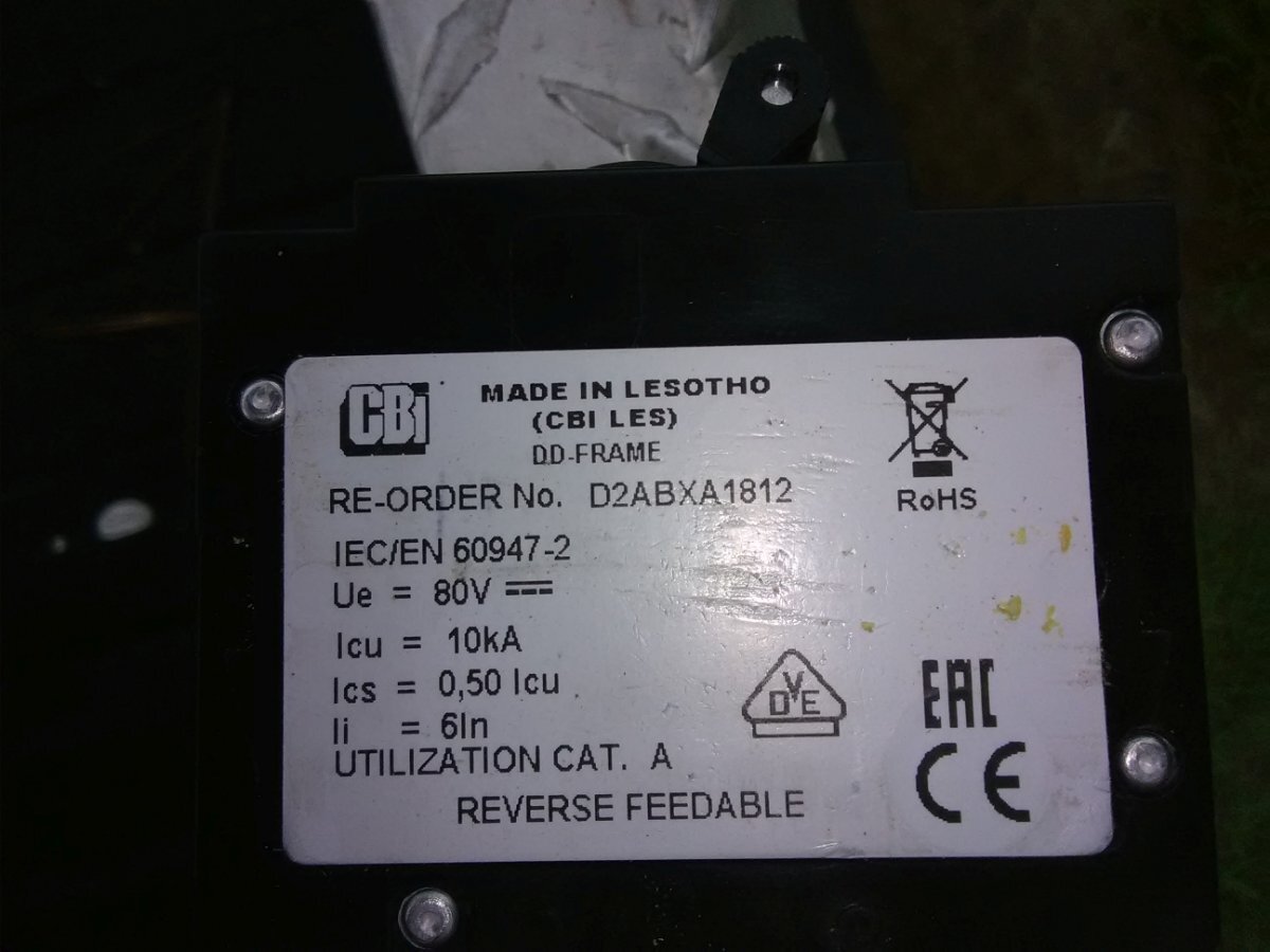
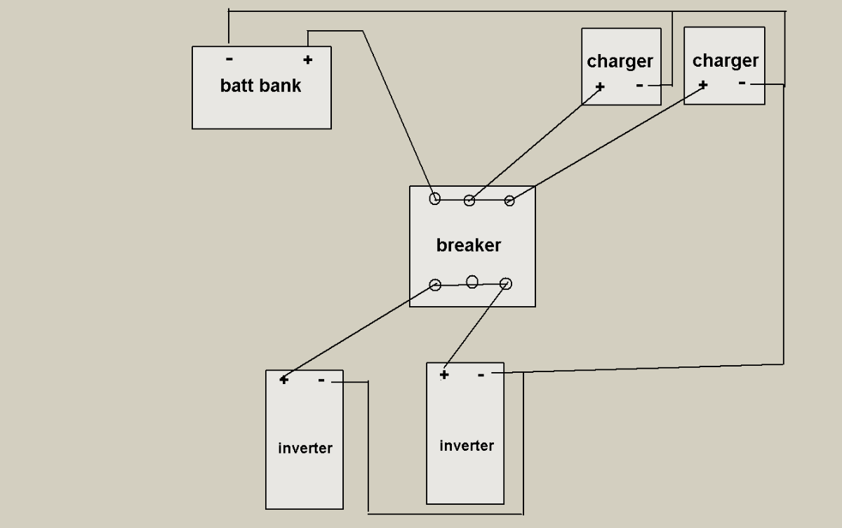
1 hour ago, Bossrox said:Here's the label & schematic how it was wired.
<a class="ipsAttachLink ipsAttachLink_image" href="/monthly_2021_06/3.jpg.635eba5ed31cd4d239722073f69fb7c6.jpg" data-fileid="440" data-fileext="jpg" rel=""><img alt="3.jpg" class="ipsImage ipsImage_thumbnailed" data-fileid="440" data-ratio="75" style="height:auto;" width="1000" data-src="//content.invisioncic.com/g308908/monthly_2021_06/3.thumb.jpg.af52c957ea9632386d8da0646a63c5e8.jpg" src="/applications/core/interface/js/spacer.png" />
<a class="ipsAttachLink ipsAttachLink_image" href="/monthly_2021_06/sch.png.8f0537e6f2ae3d820c5eafc6be49e0d1.png" data-fileid="441" data-fileext="png" rel=""><img alt="sch.png" class="ipsImage ipsImage_thumbnailed" data-fileid="441" data-ratio="62.6" style="height:auto;" width="1000" data-src="//content.invisioncic.com/g308908/monthly_2021_06/sch.thumb.png.c91d3c0a2b807b4c662df3cd7e223929.png" src="/applications/core/interface/js/spacer.png" />
Your breaker is manufactured by CBI Electric (Circuit Breaker Industries Lesotho).
It is one of their DD-frame breakers, family listing here: https://www.cbi-lowvoltage.co.za/content/circuit-breakers-equipment
Took a bit of digging around the website, but I finally found the proper family manual... https://www.cbi-lowvoltage.co.za/sites/default/files/downloads/DDFRAME_SERIES_DAT_6PAGES_1.14MB.pdf
I am assuming the full part number of your breaker (found by Googling the "reorder part number" and finding the full number on an eBay listing) is D-2AAMX3NBIK250BXX-XXXXXBDVAX3-X.
Mouthful there.
It breaks down as follows:
Group 1: D = DD Frame
Group 2: 2 = DD Type
Group 3: A = Front mount, rectangular aperture, standard (toggle) handle type
Group 4: A = Standard Handle
Group 5: MX = Stud terminals, M6 or 1/4-20 (100A Max)
Group 6: 3 = 3 pole metric (M6)
Group 7: N = 80vDC
Group 8: BI = Medium delay 50 / 60 Hz BS & inertia delay [Pulse Tolerance (X-In) = 16-20
Group 9: K250 = 250A
Group 10: BX = Circuit breaker (series trip, current coil in series)
Group 11: X = N/A (AUX and Alarm switches)
Group 12: XX = N/A (Voltage and Current Ratings for Dual Control, Shunt and Relay Trip Construction)
Group 13: X = N/A (Terminal Options for Dual Control, Shunt and Relay Coils)
Group 14: X = N/A (Voltage for Rocker Handle)
Group 15: X = N/A (Terminal for Illuminated Rocker)
Group 16: B = Black handle, white marking
Group 17: D = I – O and ON - OFF markings
Group 18: V = Vertical (standard mounting, line at the top) [If the breaker needs to be reverse fed, the printing will be upside down and codes 1 or 2 should be selected]
Group 19: A = Standard marking, standard handle (I – O and ON - OFF and ampere rating)
Group 20: X = N/A (Inter-phase Barrier and Terminal Cover)
Group 21: 3 = UL listed (UL489A), IEC / EN 60947-2, CE (DC [telecommunication])
Group 22: X = N/A (Safety Marks)
So I don't see anything weird with the breaker specifications itself. Not sure why it seems to be tripping at such a low voltage. Have you checked breaker polarity markings?
One other potentially of-interest finding on CBI's website is that with magnetic-hydraulic breakers, orientation has an affect on the trip current (very last FAQ here😞
<img alt="CB%20degrees-01.jpg?itok=1PmOGMp6" data-ratio="94.33" height="283" title="Mounting positions" width="300" data-src="  ?itok=1PmOGMp6" src="/applications/core/interface/js/spacer.png" />
There's a large amount of information available in the product overview PDF. I don't have time to read through it, but there might be some critical clues in there as to why the breakers aren't working as expected? https://www.cbi-lowvoltage.co.za/sites/default/files/downloads/CBI_APPLICATION_GUIDE_CAT_30PAGES_9MB.pdf
19 hours ago, Sid Genetry Solar said:Your breaker is manufactured by CBI Electric (Circuit Breaker Industries Lesotho).
It is one of their DD-frame breakers, family listing here: https://www.cbi-lowvoltage.co.za/content/circuit-breakers-equipment
Took a bit of digging around the website, but I finally found the proper family manual... https://www.cbi-lowvoltage.co.za/sites/default/files/downloads/DDFRAME_SERIES_DAT_6PAGES_1.14MB.pdf
I am assuming the full part number of your breaker (found by Googling the "reorder part number" and finding the full number on an eBay listing) is D-2AAMX3NBIK250BXX-XXXXXBDVAX3-X.
Mouthful there.
It breaks down as follows:
Group 1: D = DD Frame
Group 2: 2 = DD Type
Group 3: A = Front mount, rectangular aperture, standard (toggle) handle type
Group 4: A = Standard Handle
Group 5: MX = Stud terminals, M6 or 1/4-20 (100A Max)
Group 6: 3 = 3 pole metric (M6)
Group 7: N = 80vDC
Group 8: BI = Medium delay 50 / 60 Hz BS & inertia delay [Pulse Tolerance (X-In) = 16-20
Group 9: K250 = 250A
Group 10: BX = Circuit breaker (series trip, current coil in series)
Group 11: X = N/A (AUX and Alarm switches)Group 12: XX = N/A (Voltage and Current Ratings for Dual Control, Shunt and Relay Trip Construction)
Group 13: X = N/A (Terminal Options for Dual Control, Shunt and Relay Coils)
Group 14: X = N/A (Voltage for Rocker Handle)
Group 15: X = N/A (Terminal for Illuminated Rocker)
Group 16: B = Black handle, white marking
Group 17: D = I – O and ON - OFF markings
Group 18: V = Vertical (standard mounting, line at the top) [If the breaker needs to be reverse fed, the printing will be upside down and codes 1 or 2 should be selected]
Group 19: A = Standard marking, standard handle (I – O and ON - OFF and ampere rating)
Group 20: X = N/A (Inter-phase Barrier and Terminal Cover)
Group 21: 3 = UL listed (UL489A), IEC / EN 60947-2, CE (DC [telecommunication])Group 22: X = N/A (Safety Marks)
So I don't see anything weird with the breaker specifications itself. Not sure why it seems to be tripping at such a low voltage. Have you checked breaker polarity markings?
One other potentially of-interest finding on CBI's website is that with magnetic-hydraulic breakers, orientation has an affect on the trip current (very last FAQ here😞
<img alt="CB%20degrees-01.jpg?itok=1PmOGMp6" class="ipsImage_thumbnailed" data-ratio="94.33" height="283" style="height:auto;" title="Mounting positions" width="300" data-src="?itok=1PmOGMp6" src="/applications/core/interface/js/spacer.png" />
There's a large amount of information available in the product overview PDF. I don't have time to read through it, but there might be some critical clues in there as to why the breakers aren't working as expected? https://www.cbi-lowvoltage.co.za/sites/default/files/downloads/CBI_APPLICATION_GUIDE_CAT_30PAGES_9MB.pdf
All that technical data is over my head but it says on the label, reverse feedable which I'd assume means it's bi-directional? Another thing that concerned me was the terminals size, about 1/4 to 5/16's studs. That seems rather wimpy for handling a 250 amp load. I'm kinda wondering what all the hoopla is about using breakers anyways. All the electronics have their own built in protection so the only hazard I can see is if the battery cables ever get shorted out & that's something that would rarely happen on it's own using proper wiring size & more than likely only happen while you were wiring them & crossed some wires & in the event of a battery going into a fatal thermal overload, a breaker would be worthless anyways. Just my opinion it's over paranoia for a rare risk.
All that technical data is over my head but it says on the label, reverse feedable which I'd assume means it's bi-directional? Another thing that concerned me was the terminals size, about 1/4 to 5/16's studs. That seems rather wimpy for handling a 250 amp load. I'm kinda wondering what all the hoopla is about using breakers anyways. All the electronics have their own built in protection so the only hazard I can see is if the battery cables ever get shorted out & that's something that would rarely happen on it's own using proper wiring size & more than likely only happen while you were wiring them & crossed some wires & in the event of a battery going into a fatal thermal overload, a breaker would be worthless anyways. Just my opinion it's over paranoia for a rare risk.
In the end, I've put my 2 cents forward...the final decision is yours to make, and I will respect that.
But I will say that all LF power inverters (that I've seen) do NOT have ANY fused/safety protection on the DC input side. (Genetry inverters included.) Battery terminals are pretty much wired directly to the FETs...and that's it. In the rare risk that something could go wrong with the FETs, they and/or the PCBs literally become drafted into the "emergency fuse" realm...where you hope that enough things will blow out fast enough to stop power flow before a fire starts.
I did get a good laugh at one customer who was doing some bench inverter experiments...and couldn't figure out why their 200A GJ1-series breaker always instantly tripped whenever they tried to turn it on. Come to find out that they'd accidentally wired up the inverter in reverse. Thanks to the breaker, they were able to correct the polarity...and then everything worked perfectly.
I will note that most HF inverters tend to have inline DC-side fuses. But they're very poor at handling any sort of surge load.
Still, all that said, I don't understand why your breakers are tripping too soon. What are you using to measure the current? You might want to check the breaker orientation, see if that makes as much of a change as the CBI diagram indicated.
Uhm, you won't catch me now running things without a fuse or breaker. If you got the batteries and stuff in a outhouse in not in your house that up to you, but if its in your house such as mine at the moment I reather have fuse and breakers to keep any chance of a fire going off. Also I have what they call Fire Balls over my stuff as well, if a fire did break out, that fire ball would set off and supposed to exstingush 400sq of space per ball. that room that I got my stuff in is only 4 by 3. well under 400sq, and I got three fire balls in there lol. if the GS inverter had caught fire it would have shown up at sean door step cover in it lol.
I already working on ducting cold air into that room, as those fans on the GS pushes all the air out of the room when they kick on, which is fine, but I want to make sure cold air is being forced in the room.
I have what they call Fire Balls over my stuff as well, if a fire did break out, that fire ball would set off and supposed to exstingush 400sq of space per ball
I think I will get a Fire Ball . Walmart sell for 53 dollars . Thank you for the information .
I have what they call Fire Balls over my stuff as well, if a fire did break out, that fire ball would set off and supposed to exstingush 400sq of space per ball
I got minme off of amazon, probley a lot cheapier. Make sure its close to where you think the fire will show up, cause as soon as flames hit it, it will scream and then exploded. Not had one do it, but from what I read, its a sight to see.
As well as its rated for all sorts of flame, so it should work, hope to never find out.
Sid, I've just about had it with the delay getting my inverter out, I msg'd Sean yesterday for a status with no reply thru today. You said it should have gone out last week. If that frickin' thing isn't on it's way by the end of the week, I'm cancelling the order & shopping elsewhere & this experience will get posted on youtube. What's it gonna be?