PLEASE NOTE: If you had an account with the previous forum, it has been ported to the new Genetry website!
You will need to reset the password to access the new forum. Click Log In → Forgot Password → enter your username or forum email address → click Email Reset Link.
27 minutes ago, Richard said:Just ordered another 6k because we're going to retire that big, ol pig central AC on the roof. (It's amazing how much your load can be reduced by getting rid of old ****. Dryer, refig, washer...now ac...this new stuff doesn't really have a very long payback period...)
Now some questions: does this mean you're giving up, or just delaying daisy chain? What's the procedure for converting the split phase to single phase on the inverter (assuming it's a configuration setting and assuming it's already a feature)?
It works.
on my ssytem you take two breakers l1 black wire and l2 red wire. and your ground and N wire to the N. You take your two black wire and put on the master system, and a ground and N wire to the N unless you get a 104 then it be yellow and white to n on the output . with a seperate wire on one of the L out then on the slave you have both red wire and yellow white or bare and white to N same as master with the extra wire from the master going to L1 input of slave. that leaves your l1 and N on your master for charging feature.
Also please note that you need to let sean or Sid know that you are doing this. other wise it won't work on just a normal setup. you can do it with one wire, but I think it would be simple to leave it at two wire to breaker to reduce the work around to doing one wire.
It works.
Also Dasy do work, Sid is just haveing to tweek it more. its in my case that I'm running ashort run to my breaker less then 10 foot and it causeing a issue cause the inverter don't see the change fast enough to keep up and causes it to shut down. If your running a longer run which Sid can tell you how many foot needed then it works fine.
Now some questions: does this mean you're giving up, or just delaying daisy chain? What's the procedure for converting the split phase to single phase on the inverter (assuming it's a configuration setting and assuming it's already a feature)?
Parallel mode is tricky at best; definitely not throwing in the towel with the feature, it just needs fully tested to our satisfaction before shipping it.
I can test things on my bench and have them work well--but need someone else (i.e. Sean) to test it and verify that it works for him as well. The last parallel tests (which passed my tests) didn't work at all on his bench--which is why I've revised it. Now it's just a matter of his finding time to test the revised code, and see if it works better.
I'm recommending split-phase sync to @the-blind-wolfsimply because he's been waiting sooooo long, and it's a solution that'd get him 12kw total output, with solid surge capability, right now.
Converting split phase to single phase on the inverter...it's going to void your warranty, for sure (as it's a rather risky job if you don't know exactly what's going on):
- Void the software warranty, then CFG -> System -> System Setup -> set output to 120v (instead of 240SP) [note: it may use 110 and 220 instead of 120 and 240; same difference]
- this should bump the output voltage to ~100-140vAC (it'll need recalibrated to 120v out)--NOT safe to run big loads on it in this state!
- Break the warranty sticker, and open the case (powered off and disconnected)
- Rewire the transformer output wires to the control board: wires 1,3 go to T-L1, and wires 2,4 go to T-L2. (T-N is not used now. Split phase has wire 1 -> T-L1; wires 2,3 -> T-N; wire 4 -> T-L2). NOTE: If you get a "GTM Regulate Fail" error after powering the inverter on, the wires on T-L1 and T-L2 will need swapped.
- basically this is putting the 2 output transformer taps in parallel for double the current. Split-phase mode has the 2 output taps in series for 240v center-tapped.
- Rewire the AC output wires so there's 2 wires each going to O-L1 and O-L2 (none to O-N); the doubled up wires are necessary as for a 6kw inverter that's now 50A at full load (6000 / 120 = 50). Keep in mind that the hall sensor needs to be wired up the same, with the L1 and L2 wires running through it in opposite directions (for proper load registering on the LCD screen)
- if you're wanting to use AC input...
- make sure the solder jumper (clearly marked) is jumped to 240v, not 120v -> system setup input voltage will need set for 120vAC input, not 240v.
- AC input "hot" goes to I-L1
- AC input "neutral" shares the output neutral lines (going to O-L2)
Basically in a nutshell, that's how it goes; note that it does void the warranty, as changing system setup/configuration can be quite risky. Sean will be able to make the changes if necessary.
Matt. A picture for you. Hoping to ship these today. Just need to get sid to upgrade to windows 10 and we will be all set
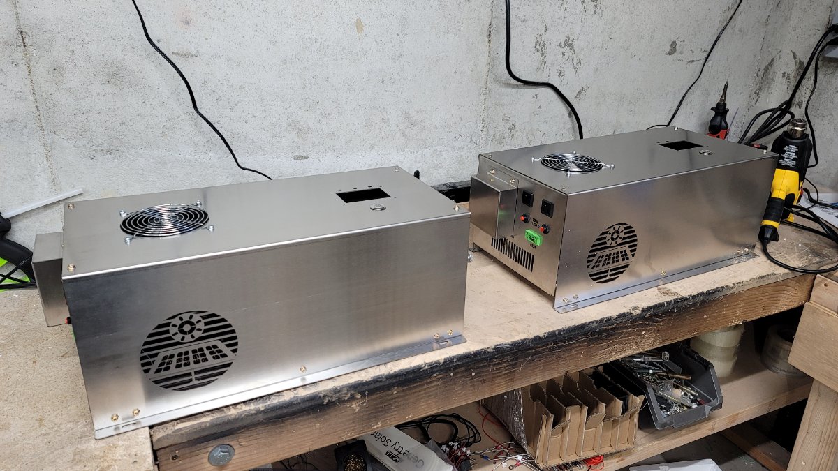
8 minutes ago, Sean Genetry Solar said:Matt. A picture for you. Hoping to ship these today. Just need to get sid to upgrade to windows 10 and we will be all set
<a class="ipsAttachLink ipsAttachLink_image" href="/monthly_2021_05/20210517_092618.jpg.4359caff9e409743aa77ed0cf6891d1e.jpg" data-fileid="329" data-fileext="jpg" rel=""><img alt="20210517_092618.jpg" class="ipsImage ipsImage_thumbnailed" data-fileid="329" data-ratio="56.2" style="height:auto;" width="1000" data-src="//content.invisioncic.com/g308908/monthly_2021_05/20210517_092618.thumb.jpg.dc35f2e8ea6f651e848d0a874b0cd7f0.jpg" src="/applications/core/interface/js/spacer.png" />
Are you going to show off them on a video? and remeber I can't see the pic 😛
Update 9:42 AM
Are you going to show off them on a video? and remeber I can't see the pic 😛
Everyone here can describe the beauty to you 😉
QuoteConverting split phase to single phase on the inverter...it's going to void your warranty, for sure (as it's a rather risky job if you don't know exactly what's going on):
Didn't read beyond this..
I'll read it sometime when I have more time....
Can I get 2 configured the same as TBW and ship back the original?
Getting to 12k with 2 of your relatively light inverters was a main attraction...
Didn't read beyond this..
Ha, no prob.
Stay tuned for a split-phase sync video hopefully coming up today or tomorrow; we can discuss your system setup and what's best for your needs. Parallel is still in the works, awaiting testing--but for those who want solid surge capability, and a much more stable option, split-phase sync is definitely something to look into.
At 120v it's half the power. I changed out the upper element in my tank to 120v 2000 watt & a 240v 3500 watter in the bottom which at 120v will use 1750 watts but you are correct, lowering the element wattage just delays the time it takes to heat the water. A 500 watt element doesn't exist 'cuz it would take forever to heat up a tank. A 1500watt 120v is the smallest I've ever seen.
500 Watt units do exist but are a specialty item. Instead of the usual size tapered thread opening, they use 1/2" NTP. They would make an excellent dump load when you had too much current available for your batteries to absorb. Problem is, they are limited to 10 PSI. We used some similar units back in the 80s to provide humidity in growth chambers.
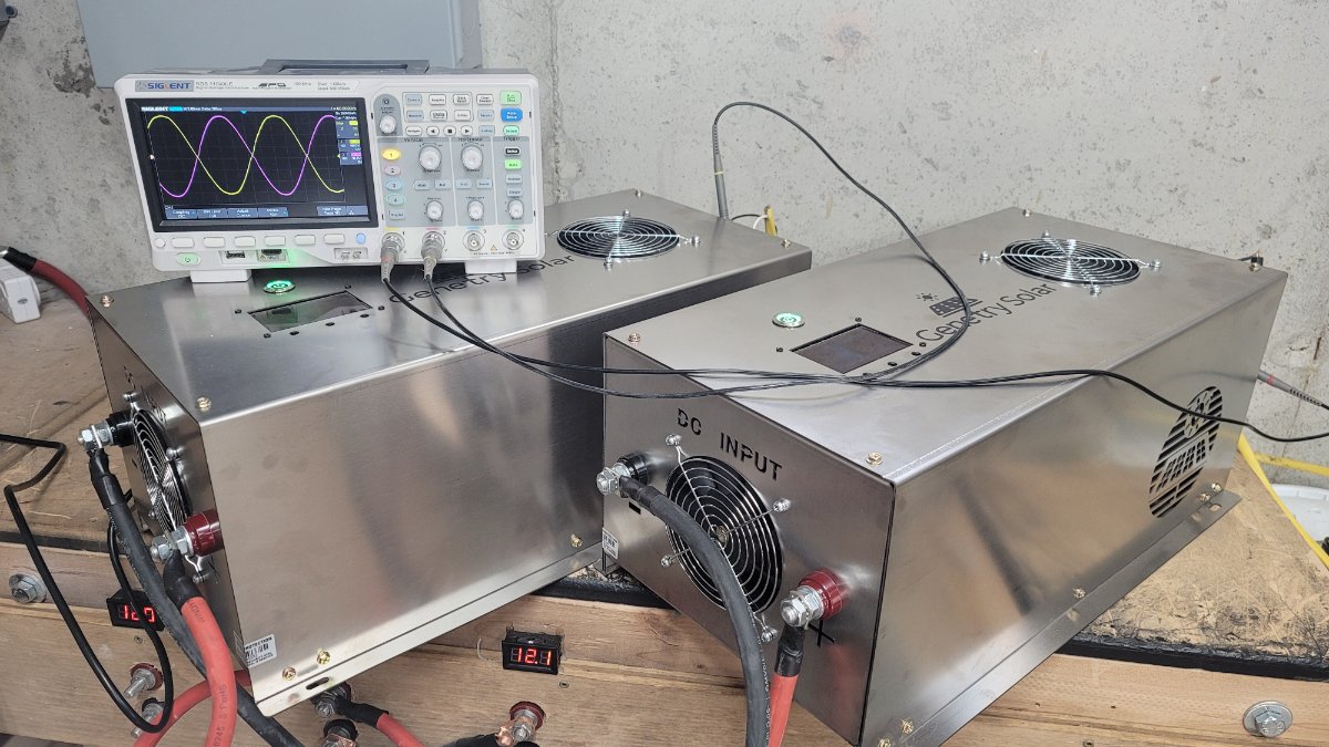
Your inverters running in split sync mode. Put almost 4kw between the two. Working out great.
17 minutes ago, Sean Genetry Solar said:Your inverters running in split sync mode. Put almost 4kw between the two. Working out great.
Yep saw the vid just now. I want to know the amprage you pulling so please let me know when you doing load test. how much power is being pulled at 4k and such.
Just now, The Blind Wolf said:Yep saw the vid just now. I want to know the amprage you pulling so please let me know when you doing load test. how much power is being pulled at 4k and such.
It will be somewhat difficult to accurately measure, but a rough calculation can be determined with Ohm's Law. 4kw * 1.1 (allowing 10% loss, i.e. 90% efficiency) = 4,400W / 24v = 183.3A off the batteries.
At full 12kw total load across the 2 inverters, that's a cool 550 amps at 24v.