PLEASE NOTE: If you had an account with the previous forum, it has been ported to the new Genetry website!
You will need to reset the password to access the new forum. Click Log In → Forgot Password → enter your username or forum email address → click Email Reset Link.
Hi Sean and Sid,
I have been running the inverter for a while and all has been good other than the KWh being off by a factor of 10 and the number of hours reading as -1 on the wifi.genetrysolar.com site. Not a big deal but something to fix when you get around to it.
My question is I have 2 panels in my house setup. The main one is fed from the grid and the second one is setup as a critical loads panel and is only fed by the inverter. What is the default voltage that the GS inverters are setup to for the input as I would like to connect the inverter's input to the main panel so that it can charge the batteries or work in DC Priority Mode. What is the input voltage for the inverter if I never asked for it to be set to anything specific? I would assume it is 240VAC L1---L2 by default but I don't want to hook it up till I know for sure.
Have a great day,
-Dave
all has been good other than the KWh being off by a factor of 10
Sorry, software bug on the WiFi board through 1.1r1. Found, confirmed bug 😉. Need to release 1.1r2 to fix that, but want to get genstart functionality added first...
and the number of hours reading as -1 on the wifi.genetrysolar.com site
Is the hourmeter reading correctly on the WiFi board? When initially set up, the hourmeter should read 0. This is kinda a new one, as the hourmeter reads correctly online on my house inverter running 1.1r0. (Yeah, kwh is off by the factor of 10...only 609.1KWh.)
What is the default voltage that the GS inverters are setup to for the input as I would like to connect the inverter's input to the main panel so that it can charge the batteries or work in DC Priority Mode. What is the input voltage for the inverter if I never asked for it to be set to anything specific? I would assume it is 240VAC L1---L2 by default but I don't want to hook it up till I know for sure.
Really not sure. Has come to our attention that the manufacturer might have gotten a wire or 2 mixed up internally, which could slightly complicate the testing. There technically are 3 factors that determine the AC input voltage setting (for now--the yet-to-be-ordered Rev. C boards hopefully will have a user-configurable/auto AC voltage input setting).
- Internal Wiring
- check this by measuring the AC voltage across O-L1 (output L1) and I-N/L2 (input neutral/L2) with the inverter running. If you read 120v or 240v, that's the hardwired input config. 0v or other stuff indicates a factory miswiring--unfortunately one that we only discovered AFTER we started shipping inverters.
- CPU configuration
- check this by reading the end of the first line on the STAT screen (Inverter model). "SPB" = Split Phase "Big" 240v. "SPL" = Split Phase "Little" 120v.
- a solder jumper has to be configured during setup
- if the 2 above checks both result in the same voltage, you can check this by applying the above ascertained voltage to the 2 input terminals. If the LCD registers it in the AC Input box, you are good to go. If it reads a really weird voltage, then the jumper isn't set right. (Ugh!)
My question is I have 2 panels in my house setup. The main one is fed from the grid and the second one is setup as a critical loads panel and is only fed by the inverter.
I don't like to preface everything with a "but", but I assumed that the market we were reaching was Power Jack customers that wanted something better. Admittedly I started out trying to re-use as much of Power Jack's design as I could--but as of the next revision, there won't be a single PJ part in the inverter 😉.
So I kinda got caught blindsided with a big issue here...the ubiquitous ground-neutral bonding effectively will connect 2 of the 3 wires to the inverter at all times, which is a huge problem. Sort of covered here:
<iframe allowfullscreen data-embedauthorid="21" data-embedcontent="" data-embedid="embed9433909109" scrolling="no" style="height:295px;max-width:500px;" data-embed-src="/topic/101-isolating-the-neutral/?do=embed&comment=1481&embedComment=1481&embedDo=findComment">
Obviously, I will fix this in the next board revision--but in the meantime, we still have a bit of an issue with the inverters already in the field ;-). If you can electrically isolate the Neutral and Ground (as the 2 are pretty much synonymous) on the "essential loads" panel (so it is COMPLETELY disconnected from the grid--not even a shared ground)...then this should work in 240v mode.
If your inverter is setup for 120v, then this is a moot point and not a problem at all.
Basically, I shoulda switched both AC input terminals on the PCB. That would completely eliminate this entire problem. You bet the next revision board will have this fixed...
Thanks for the quick response Sid.
1. Internal Wiring
So I just checked and O-L1 (output L1) to I-N/L2 (input neutral/L2) with the inverter running reads at 238.7 VAC. I read the same voltage across output L1 to L2. So It appears the input is wired correctly for scenario 1.
2. CPU Configuration
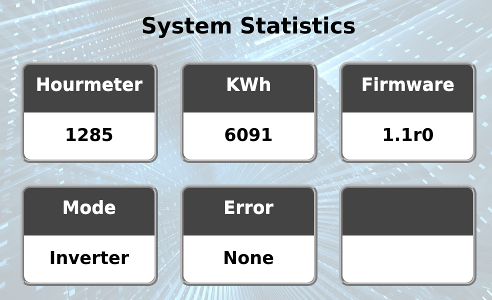
As far as this goes, I am not seeing anything about "(Inverter model). "SPB" = Split Phase "Big" 240v. "SPL" = Split Phase "Little" 120v." on the STAT screen of the inverter but I may be looking in the wrong place. Pictures below:
<a class="ipsAttachLink ipsAttachLink_image" data-fileext="jpg" data-fileid="276" href="/monthly_2021_04/20210423_213710_HDR.jpg.aad71c5b2d18414e6270ca18e601b757.jpg" rel=""><img alt="20210423_213710_HDR.thumb.jpg.cc6cc7162883f20e0122af56614a57ed.jpg" class="ipsImage ipsImage_thumbnailed" data-fileid="276" data-ratio="74.90" style="height:auto;" width="1000" data-src="//content.invisioncic.com/g308908/monthly_2021_04/20210423_213710_HDR.thumb.jpg.cc6cc7162883f20e0122af56614a57ed.jpg" src="/applications/core/interface/js/spacer.png" />
<a class="ipsAttachLink ipsAttachLink_image" data-fileext="jpg" data-fileid="277" href="/monthly_2021_04/20210423_213756_HDR.jpg.10df0f8babd79d054022715f3aefb6ed.jpg" rel=""><img alt="20210423_213756_HDR.thumb.jpg.fff44482c8458f5d589c761885b2d63b.jpg" class="ipsImage ipsImage_thumbnailed" data-fileid="277" data-ratio="74.90" style="height:auto;" width="1000" data-src="//content.invisioncic.com/g308908/monthly_2021_04/20210423_213756_HDR.thumb.jpg.fff44482c8458f5d589c761885b2d63b.jpg" src="/applications/core/interface/js/spacer.png" />
<a class="ipsAttachLink ipsAttachLink_image" data-fileext="jpg" data-fileid="278" href="/monthly_2021_04/20210423_213833_HDR.jpg.a609fad4b14d4dd7aa612f9d74c9ba14.jpg" rel=""><img alt="20210423_213833_HDR.thumb.jpg.f9f9b71a172a9d6f76963fea8e9a5607.jpg" class="ipsImage ipsImage_thumbnailed" data-fileid="278" data-ratio="74.90" style="height:auto;" width="1000" data-src="//content.invisioncic.com/g308908/monthly_2021_04/20210423_213833_HDR.thumb.jpg.f9f9b71a172a9d6f76963fea8e9a5607.jpg" src="/applications/core/interface/js/spacer.png" />
I will also include images of what I see on wifi.genentrysolar.com and the main screen of the inverter:
<a class="ipsAttachLink ipsAttachLink_image" data-fileext="jpg" data-fileid="279" href="/monthly_2021_04/20210423_213903_HDR.jpg.7bf71a2af059efc807d7caa74c1a11bb.jpg" rel=""><img alt="20210423_213903_HDR.thumb.jpg.036fb16a7d237d7bb2412625bfb74772.jpg" class="ipsImage ipsImage_thumbnailed" data-fileid="279" data-ratio="74.90" style="height:auto;" width="1000" data-src="//content.invisioncic.com/g308908/monthly_2021_04/20210423_213903_HDR.thumb.jpg.036fb16a7d237d7bb2412625bfb74772.jpg" src="/applications/core/interface/js/spacer.png" />
<a class="ipsAttachLink ipsAttachLink_image" data-fileext="PNG" data-fileid="280" href="/monthly_2021_04/315511118_wifigenetrysolarsnip1.PNG.965d8c725d92d6fce0772a0087fdb7f4.PNG" rel=""><img alt="422230403_wifigenetrysolarsnip1.thumb.PNG.fef6c01f80fe3e873e2f954469e59d85.PNG" class="ipsImage ipsImage_thumbnailed" data-fileid="280" data-ratio="116.10" style="height:auto;" width="646" data-src="//content.invisioncic.com/g308908/monthly_2021_04/422230403_wifigenetrysolarsnip1.thumb.PNG.fef6c01f80fe3e873e2f954469e59d85.PNG" src="/applications/core/interface/js/spacer.png" />
<a class="ipsAttachLink ipsAttachLink_image" data-fileext="PNG" data-fileid="281" href="/monthly_2021_04/984405255_wifigenetrysolarsnip2.PNG.b266a6d6e3d182fa0c3ea023cde8a02c.PNG" rel=""><img alt="911843982_wifigenetrysolarsnip2.thumb.PNG.29de8b932c531d8c4ab0955b4958e425.PNG" class="ipsImage ipsImage_thumbnailed" data-fileid="281" data-ratio="122.95" style="height:auto;" width="610" data-src="//content.invisioncic.com/g308908/monthly_2021_04/911843982_wifigenetrysolarsnip2.thumb.PNG.29de8b932c531d8c4ab0955b4958e425.PNG" src="/applications/core/interface/js/spacer.png" />
Hopefully that helps.
In regards to the neutral/ground bonding situation:
The main panel (attached to the grid) has neutral and ground bonded and I would need to rewire the entire panel and un-bond the neutral busbar to the chassis ground to make that happen, so that is likely out as un-bonding the neutral would go against code.
The critical loads panel is bonded to the main panel as far as ground is concerned both physically due to conduit going between knockouts and also via a 6 gauge ground wire attaching the main panel grounding bus bar to the second panel ground bus bar.
In the critical loads panel, the ground and the neutral bus bars are not bonded together and I have all of the grounds and neutrals separated out as you would per code for a subpanel. I have the inverter chassis ground currently grounded to the critical loads subpanel so I am assuming the best option is going to be to unground the inverter chassis and leave the inverter chassis floating in order to use the AC input?
At least I believe that should work as their would be no physical connection to ground on the inverter and the Neutrals in the critical loads panel are already isolated.
Have a great evening,
-Dave
Well, I think I see part of the problem...firmware is 1.0r22. I believe charge/ATS were disabled in this version anyhow.
This also explains why the Hourmeter reads -1 on the webpage.
Try to get this connected to your WiFi network, set the Update Branch to "Revision", exit the "WiFi" page (it saves settings when you leave the page), power cycle the inverter, and see if it finds 1.1r1 to download. Please note that due to a bug fixed in 1.1r0, you may have to retry the update a dozen times or so before it'll finally actually take it (instead of complaining "Firmware file corrupted".)
Or you can wait a few days and I'll try to get 1.1r2 out. No promises though...SO much going on.
The main panel (attached to the grid) has neutral and ground bonded and I would need to rewire the entire panel and un-bond the neutral busbar to the chassis ground to make that happen, so that is likely out as un-bonding the neutral would go against code.
Not a problem for the input/main panel. It can be left grounded/bonded.
The critical loads panel is bonded to the main panel as far as ground is concerned both physically due to conduit going between knockouts and also via a 6 gauge ground wire attaching the main panel grounding bus bar to the second panel ground bus bar.
Inverter ground is nothing more than a connection to the chassis and some light capacitor decoupling to the DC side. This can remain grounded.
The issue is if the Output Neutral has ANY connection to the grid-neutral-bonded Ground, it will backfeed power into the inverter through O-L2 and O-N. Best case, the inverter will refuse to turn on (as there's power being forced into it)...worst case, it'll blow up (if power is introduced while it's running in inverter mode).
You can test this hypothesis by wiring the inverter up as you want to, turn the breaker panels on...AND LEAVE THE INVERTER OFF! If you measure 240vAC on O-L1 and O-L2, power is getting backfed through the ground/neutral bonding mess via O-L2 (which is internally tied to I-N/L2) and O-N.
So I was able to update the firmware and current version now reads as 1.1r1. The update took on the first try without any real issues. I did have to go back into the inverter settings and calibrate the readings on the display a bit but it is now working and shows up as SPB at the end of the inverter model on the STAT menu.
I then powered off the inverter and connected the 240v input from the main panel and was able to verify no voltage on the O-L1 and O-L2 terminals.
I powered on the inverter and I was able to verify step 3 as a success as well so now the input is connected and also working and did verify before powering anything up that the neutral on the output of the inverter was isolated from the bonded ground and neutral in the main panel with a meter so that seems to be good.
Everything on the inverter end seems to be doing what it is supposed to and I went through and setup all of the charging parameters except for the charging amps as it would not let me set it. I did a test of UPS mode and it seemed to work like it was supposed to.
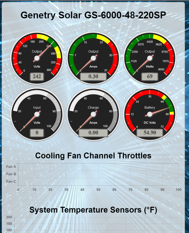
Here is what I see on the wifi.genentrysolar.com page after the update:
<a class="ipsAttachLink ipsAttachLink_image" href="/monthly_2021_04/1221437378_Afterupdate1.PNG.a933ab16526e9762188b1babb0f4f5b3.PNG" data-fileid="283" data-fileext="PNG" rel=""><img class="ipsImage ipsImage_thumbnailed" data-fileid="283" data-ratio="143.40" width="523" alt="6672251_Afterupdate1.thumb.PNG.1c01c90cc53f938db8015be41bf127fc.PNG" data-src="/monthly_2021_04/6672251_Afterupdate1.thumb.PNG.1c01c90cc53f938db8015be41bf127fc.PNG" src="/applications/core/interface/js/spacer.png" />
<a class="ipsAttachLink ipsAttachLink_image" href="/monthly_2021_04/454845228_Afterupdate2.PNG.e6ed00248b16f29db951e75470f29198.PNG" data-fileid="284" data-fileext="PNG" rel=""><img class="ipsImage ipsImage_thumbnailed" data-fileid="284" data-ratio="118.67" width="632" alt="1820029832_Afterupdate2.thumb.PNG.39065bc3f2c555f76b84aff6d96ce77e.PNG" data-src="/monthly_2021_04/1820029832_Afterupdate2.thumb.PNG.39065bc3f2c555f76b84aff6d96ce77e.PNG" src="/applications/core/interface/js/spacer.png" />
It appears the hours are now reading fine. The KWh should read 39.4 as you already know. The model shown at the top of the page along with the gauges seem to have changed from what it used to show (almost looks like it can't ID the inverter) and it does not show the input voltage but the inverter is reporting the input on its screen correctly.
Have a good day,
-Dave
Everything on the inverter end seems to be doing what it is supposed to and I went through and setup all of the charging parameters except for the charging amps as it would not let me set it.
Input Amps...not implemented yet. This is intended as a sort of "input amp limit", i.e. throttle charging back if there's other loads pulling from the input circuit--so we don't overload the input circuit.
Charge current is a percentage right now; I haven't calibrated/calculated it out.
The model shown at the top of the page along with the gauges seem to have changed from what it used to show (almost looks like it can't ID the inverter) and it does not show the input voltage but the inverter is reporting the input on its screen correctly.
Humph. And I'm not available tomorrow to fix bugs...!
Need to look into this. Not sure why the inverter heading is broken now--I didn't touch that code on the inverter side. Its basically reading absolute maxed out numbers, which is weird if the inverter is correctly identifying itself on the top of the STAT screen? (If you went from 1.0r22 to 1.1r1, there's a CHANCE it might have failed to copy the setup over, which would not be very good.)
The display on the wifi.genetrysolar.com site seems to have gone back to ID ing the inverter correctly. Not sure if you made a change to it but it now looks like this:
<fileStore.core_Attachment>/monthly_2021_04/1133520227_Update2.PNG.b0b9aa0fffe921e282e92ccdacc98ffe.PNG
It's not showing the AC input online, but the inverter, last I checked yesterday after the updates and testing was correctly showing the AC input status and voltage. So for now everything appears to be good.
Thanks for the help and advice for testing the input configuration.
Have a great day,
-Dave
Well, I'm glad it is properly ID'ing it, though I have no idea what was going wonky with it. Might need to check the Mosquitto server logs.
Had a bit of a scare myself today...logged in to check the house inverter while I was away from home. It was reporting the battery voltage at 61.2v--which is far above the absolute max of 58v. Scared me a bit, called a family member to check it--then a few minutes later I refreshed the page, and it went to the actual 56.4v. Got back, and all the max/min stats on both the MPPTs and inverter are no higher than 56.8--so why in the world it was displaying that, I have NO idea. Definitely not a surprise I wanted to see, for sure.
AC Input not reading...checked the code, the WiFi board is reporting it. So the issue then is simply that I haven't implemented the proper handler code on the webserver backend.
Is the max dc voltage for the GS 48v inverter 58v ? Can the GS inverter set to 62v ? I run my powerjack inverter 61 v max . The sine wave looks better at 54v and higher . The light flicker at 52 v .
Hmmm. 48v normaly runs up to 57v max charge. 58v on others. I think you have to have it configured for that before its shipped to you. Sid can say if that is the case or not, since he is the designer of the board.
I know one customer useing tesla walls had to have theirs configed to work at the odd voltage.
Is the max dc voltage for the GS 48v inverter 58v ? Can the GS inverter set to 62v ? I run my powerjack inverter 61 v max . The sine wave looks better at 54v and higher . The light flicker at 52 v .
Yes, a GS inverter should be able to run at 62v without any issue. Absolute maximum DC input is 75vDC, though I cannot recommend running a 48v GS inverter that high.
A 48v GS inverter will run a 240vAC pure sine wave down to 45.2vDC in (at no load). And there should not be any flickering in the lights UNLESS there is a wave-skipping load attached to the inverter (laser printers, some hot air guns, etc.)
Poor sine wave under 54v...that's because of the PJ transformer specification. They're usually specced 36v -> 230v, so the minimum DC voltage required for a 240vAC pure sine wave output is mathematically 53.1v. (36v / 230v = 0.1565 multiplier * 240vAC output = 37.565vAC into the tranny for 240vAC out * 1.414 [= square root of 2] = 53.117vDC required for a pure sine at no load.)
52v light flicker...that's the fault of the CPU firmware, which doesn't have a "no-change" option in the regulation. There will be numerous "nodes" in the regulation of a PJ inverter, dependent on the load level, load type and battery voltage.
Is the max dc voltage for the GS 48v inverter 58v ? Can the GS inverter set to 62v ? I run my powerjack inverter 61 v max . The sine wave looks better at 54v and higher . The light flicker at 52 v .
Thank you for all the information here and in youtube . I move all my lithium ion electric car batteries out the garage which is 120 degree in summer to the backyard patio which is 100 degree . I only need to run your 12kw GS inverter for the 4 ton heat pump 8 hours in the city to save 400 dollars a month in utility cost . I run 16s for the battery . The summer rate is 4 times the rate in winter so that why the utility company do not like DIY installation .
The 12k GS inverter is not out yet, probley will be a few more months at the most. Also 100 degress is pretty hot to run a GS inmverter. Its needs to be at least 75 degrees, if you get close to 100 degrees, you inverter will will either shut down due to over heating or reduce power output because of over heating.
Is the max dc voltage for the GS 48v inverter 58v ? Can the GS inverter set to 62v ? I run my powerjack inverter 61 v max . The sine wave looks better at 54v and higher . The light flicker at 52 v .
12kw inverter isn't available just yet--we're still working out design issues. Hopefully will be available in a few months...pretty much mid-summer at best.
GS inverters should be OK at full load with ambient temps of 100 degrees Fahrenheit. Much above that, there's a thermal derating for the max load (shutdown at internal temps of 180F). Keep in mind, however, that the inverter is NOT rated for outdoor installation/use. Batteries won't be happy getting wet either.
16S Li-Ion (not LiFePo4)? That's 66.4v near fully charged (4.15*16)...pretty high up there TBH.