PLEASE NOTE: If you had an account with the previous forum, it has been ported to the new Genetry website!
You will need to reset the password to access the new forum. Click Log In → Forgot Password → enter your username or forum email address → click Email Reset Link.
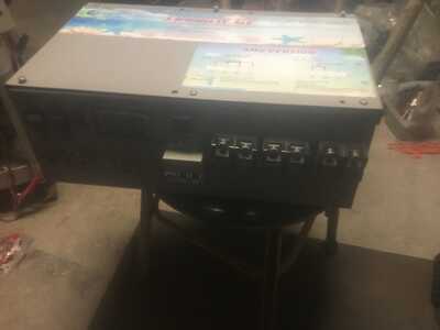
I've been using a 24v, 4000w (labeled 8000w?) PJ inverter for the last two years without issue. It is a barebones v11 design with no charger or lcd. I've always just hooked things up to the one 110v AC outlet on the back of the unit. It has been working mostly 24/7 as long as I keep a really old window AC unit away from it... I've gotten it up to 3600w at one point for a bit just to test it out (yikes for one outlet!), but typically I keep it under 2000w, often under 1000w.
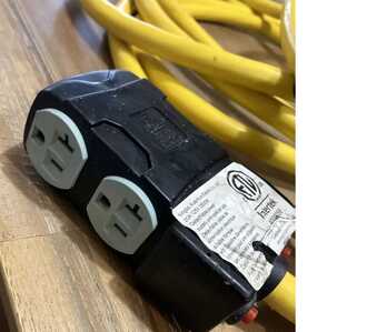
i want to hook it up as 220v using the screw terminals and run it into some proper AC breakers. I've found an inexpensive 4 prong lockable RV extension cable someone is almost giving away. It is 25ft of 10g wire (x4) and terminates into a small box with two 110v outlets and some red reset buttons. I was thinking of cutting off the 4 prong plug and wiring directly to the breakers. The RV cable is labeled Intertek 4000058.
This seems to be a way to power 110v devices, but also have the inverter hooked up as 220v so I could start charging my EV (1000w-2000w, nothing crazy). I was wondering if I'd need to try to balance the load over the two different sets of outlets? It is the AMG version and I don't know what 50% rated power for 110v means in PJ marketing speak. Does it mean if I'm just using the four 110v outlets from this RV cable I'd want to limit it to 1500w or so for each leg? They are spec'd at 20a.
There was some mention that v11 has no output capacitor on the "other" leg of 110v. Can someone let me know what type I'd need? I think I read polyester, but I the ones on it now have no farad rating that I could see. Would there be any use to upgrade all those capacitors while i'm at it?
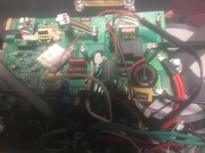
Am I also correct in thinking I could do away with those fuses on the output AC if I put the output directly into the AC breakers? I occasionally notice the inverter won't start if the sole 110v output socket is slightly jiggled by the extension cord I currently use. It isn't the cord. The output side of the inverter looks a mess, like it was soldered by a toddler. I'm not sure which parts are occasionally touching, but I'd prefer to replace what I can while I'm in there and tidy things up if possible.
Thanks.
This seems to be a way to power 110v devices, but also have the inverter hooked up as 220v so I could start charging my EV (1000w-2000w, nothing crazy). I was wondering if I'd need to try to balance the load over the two different sets of outlets? It is the AMG version and I don't know what 50% rated power for 110v means in PJ marketing speak. Does it mean if I'm just using the four 110v outlets from this RV cable I'd want to limit it to 1500w or so for each leg? They are spec'd at 20a.
So the "50%" is actually a fair point on PJ's side. Ampacity (current flow) is what generates heat in conductors, regardless of the voltage potential. Thusly we find that 4,000W / 240v = 16.67A, and 2,000W / 120v = 16.67A.
Yes, you'd want to try to balance the loads if you're running it near the max (which as you noted is closer to 4kw!), otherwise the transformer heat will be significantly increased. The transformer winding spec is the weakest point of the inverter at any rate.
There was some mention that v11 has no output capacitor on the "other" leg of 110v. Can someone let me know what type I'd need? I think I read polyester, but I the ones on it now have no farad rating that I could see. Would there be any use to upgrade all those capacitors while i'm at it?
Yeah, a 4.7uF 400v (red) polyester (NOT electrolytic!) is most common--but if you've got some oil-filled motor-start caps of similar spec (4.7-10uF) laying around, just throw one of those on there 🤣 . It's worth noting that oversizing these capacitors will result in higher no-load current draw on the inverter. The main purpose of these caps is to filter out the 24KHz SPWM modulation that does come through the transformer; beyond that, they don't serve much purpose.
Am I also correct in thinking I could do away with those fuses on the output AC if I put the output directly into the AC breakers? I occasionally notice the inverter won't start if the sole 110v output socket is slightly jiggled by the extension cord I currently use. It isn't the cord. The output side of the inverter looks a mess, like it was soldered by a toddler. I'm not sure which parts are occasionally touching, but I'd prefer to replace what I can while I'm in there and tidy things up if possible.
You've got fuses in addition to the breakers on the output of the inverter? I dunno what they're doing these days anymore!
I think I got the general idea of what you're thinking, i.e. tap directly into the transformer secondary on the "AMG" terminal on the back of the inverter? I don't see any problem with that.
Thanks for the response. Noticed last night PJ soldered a ring terminal to one of the fuse holders... I meant get rid of those fuses and use a proper circuit breaker (not built-in by PJ). I found some awesome dc breakers at the renew store that also work with ac and are din rail compatible.
The Tesla charger I have is capable of around 40amp charging, which is usually derated to around 32a / 7kw. I can always lower the amps to get down to 1-2kw (for this PJ at least).
What would be your recommendation if I purchased a 6kw Genetry Inverter? I haven't found anyone expressing any issues with Genetry Inverters and EV charging, but haven't looked in a while. When I was looking it felt like mostly the issues were related to the Tesla charger not liking the grounding on various inverters.
By the way, you sent me some photos of your 32650 setup a while back. Thanks again. I currently have around 1300 of them sitting on my dining room floor right now ready for some business.
By the way, you sent me some photos of your 32650 setup a while back. Thanks again. I currently have around 1300 of them sitting on my dining room floor right now ready for some business.
Such is the fun of online systems...the same person showing up with different names in different platforms ;-). You probably had an older forum account under a different name, I presume?
The one thing I would recommend doing: Buy a proper spot welder and use the nickel strips to spot-weld the cells together. Don't use a soldering iron and wire like I did ;-). FWIW I've purchased a couple of the cheapy Chinese spot welders from eBay/Amazon that run off a 12v battery...and they're all junk. They work for a dozen or so lousy spot welds, then *poof* blow out.
The best one I've purchased so far was an ultracapacitor spot welder. And...turns out the internal ultracaps were removed from a decomissioned electric bus "hybrid" pack (read "faulty"!) One of the two ultracaps ended up having an internal bad connection that would randomly "open". Whack the unit on the tabletop and it'd usually do a couple more welds. 4 videos to the seller later, and a month of shipping time, and they sent a replacement capacitor set--which has worked fine since.
What would be your recommendation if I purchased a 6kw Genetry Inverter? I haven't found anyone expressing any issues with Genetry Inverters and EV charging, but haven't looked in a while. When I was looking it felt like mostly the issues were related to the Tesla charger not liking the grounding on various inverters.
Recommendation for what?
I can't recall hearing of issues with Genetry inverters and Tesla chargers; the most problematic appliances thus far (at least to my recollection) have been washing machines. One customer complained about moire in an analog CCTV system; I think increased AC output filtration helped a lot.
I think I both forgot my password and this forum updated.
I wish I would have listened to the hundreds of people saying to avoid the cheap spot welders, and I avoided the cheapest, but got one that wouldn't recharge after a short time. I believe I used a 12v adapter to charge it instead of a 5v (usb-c, ugh). I have since purchased a malectrics arduino based spot welder, and then in my procrastination I came up with a different way to do it entirely. I need to make a small pack first to see if it works before I'm even willing to talk about it openly because it sounds a little nutty, but it worked well when I charged all the batteries recently. If it works and its safe it will be a lot less time than spot welding nearly 2600 ends... which is what I've been dreading.
And then a forth option is available, which I just learned about recently, is to spot weld copper directly to the end of the cell, but put nickel strip over the top of the copper. The "sandwich method" has a lot of discussion on the endless sphere forums with examples (of much smaller packs for scooters and bikes, etc). Copper doesn't have enough resistance by itself to spot weld, but the nickel adds the resistance and it appears to work well to get copper sticking directly to the cell ends. Some even use two thin strips of nickel on top, side by side, so the energy has to go from the tip, to the nickel, down through the copper, to the end of the cylinder, up through copper and then to other nickel strip to other tip.
"Recommendation for what?" I don't even know what I was trying to say there... just some reassurance that it can do sustained 6kw+ which from all accounts seems like it can. I just haven't kept up with all the user experiences. All I ever read negative (other than the genetry solar inverter isn't free) was about a person or two with initial problems, which to me just read like you guys going out of your way to fix one or two glitches out of the millions of things that can go wrong with all the crazy stuff we try to power with inverters.
I have some type of medical grade power conditioner used on a very high priced laser, but haven't spent the time to figure out exactly what is or what it does. It is heavy as sin for its size. I haven't felt the need to try it yet.
You've got fuses in addition to the breakers on the output of the inverter? I dunno what they're doing these days anymore!
I think I got the general idea of what you're thinking, i.e. tap directly into the transformer secondary on the "AMG" terminal on the back of the inverter? I don't see any problem with that.
I dunno what Jack is thinking by not making the rev11.3 control board anymore . The new blue Powerjack control board that replace the rev11.3 control board look a lot like the GS12000 watt rev C2 control board and the transformer I test with a variac has primary of exactly 32 vAC and secondary of 244 vAC output . The shell of the new 20kw Powerjack has LCD built-in and about the size of the GS12kw case .
I dunno what Jack is thinking by not making the rev11.3 control board anymore . The new blue Powerjack control board that replace the rev11.3 control board look a lot like the GS12000 watt rev C2 control board and the transformer I test with a variac has primary of exactly 32 vAC and secondary of 244 vAC output . The shell of the new 20kw Powerjack has LCD built-in and about the size of the GS12kw case .
I have a 12000 W 24v , I was trying to see if I can get it running. I ordered the replacement control board I gave all the information as possible the I received something completely different. I don’t think those PJ vendors really give an “iota “after many and many back and forth explaining all I got the same answer this an “updated board please try again “ lot of vague instructions not related the new board even though the new board requires a retrofit rainbow ribbon cable I finally gave up. It would be nice if anyone have any ideas how to install as well where to get the ribbon cable..
I ordered the replacement control board I gave all the information as possible the I received something completely different.
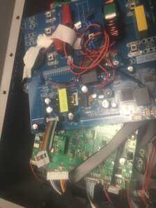
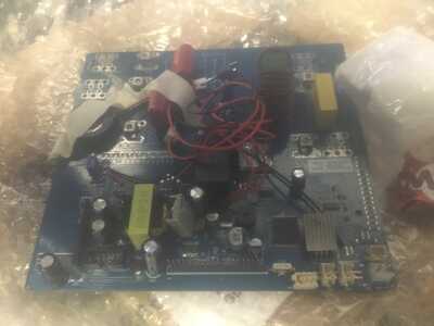
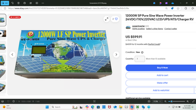
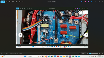
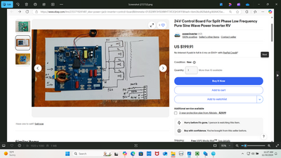
YES I order the rev11.3 control board from ebay website but got the new blue control board exactly like your picture . DO NOT connect to your inverter with the rev11.3 control board or all the mosfetts will explode and LF driver will start smoking . David from Powerjack ebay will sell the complete mainboard 200 dollars each with mosfetts and capacitors and heat sink and ribbon cable and LCD with 20 pins ribbon cable for the new blue control board 90 dollars . I will post pictures if you willing to buy the parts for repair . Ebay has picture of the blue control board in a 20kw powerjack .
@dickson,
Great! Thank you for the information, if you can please post the information / David contact how to order those replacement parts.
This is new wiring diagram from David from ebay on how to wire the new blue control board , I use a variac to verify the AMG wire L1 and Neutral and L2 . Ebay do not show LF Driver or complete Mainboard with mosfetts or LCD and 20 pins cable that need to be replace .
@Dickson, I pulled the trigger ordered the new main power mos- board , expecting to be delivered my mid- January.knowing PJ support is none existent although I was cleared and specific David and Jely asking for installation instructions., the old current connections looked a bit different from the new . My question is have you had replaced both of new blue controller as well of the main power mos-board so perhaps you maybe able to share the connections with me.
Thanks
I replaced the new blue control boaed as well the main power mos-board with capacitors and maybe able to share the connections with you .
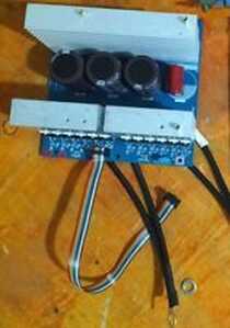
The new blue control board has a 20 pins connecter for the start button and LCD that is require to turn the Powerjack inverter on . The LCD is similar to how my GS12kw with the start button turn on the inverter . You need the 20 pins LCD screen and 20 pins cable . Let me know if David can sell you the LCD screen with 20 pins cable . Let me know if he do not have the LCD . I converted 2 old Powerjacks to the new blue control board . Be careful to install the LF driver in the right direction as the previous picture .
