PLEASE NOTE: If you had an account with the previous forum, it has been ported to the new Genetry website!
You will need to reset the password to access the new forum. Click Log In → Forgot Password → enter your username or forum email address → click Email Reset Link.
My 12000 watt AGM has been a paper weight , I have followed Powerjack recommendations replacing the mosfets , the control board etc same result , I was wondering perhaps the main board could be bad . How can I check the main board and the transformer although The transformer has 4 output leads the first two to the left goes to the Ac output and the the other two goes to the board .I have checked for continuity that was extend of my test.
any insight will be greatly appreciated
How can I check the main board and the transformer
The mainboard havs 4 mosboard and should see 4 LED light up green with inverter switch OFF and battery connectrd . The control board should be Rev 11.3 and at least 2 green LED light on when the inverter switch is ON . IF LED are all OFF or LED are blinking or the mosfets blow up then it is wrong control board or bad LF driver . The transformer can be check IF the control board is good and LED is green . The transformer 2 primary should be 32vAC to 36vAC if 48 vdc inverter . The 2 secondary is 230vAC to 240vAC . Rev 11.1 or Rev 11.0 or Rev 10.3 control board will blow up the FETs instantly . The newest AMG inverter will self test for error and not start untill error is fixed . I use my 30kw Powerjack for 8 months starting in October to power the house and the heat from the hot transformer is use to heat the room .
How can I check the main board and the transformer although The transformer has 4 output leads the first two to the left goes to the Ac output and the the other two goes to the board .I have checked for continuity that was extend of my test.
Checking the transformer...it gets a bit difficult to test with actual power. But if "nothing happens" when you turn the inverter on, then a continuity check will be more than sufficient for determining if the transformer is good.
Check also the two (?) primary leads going to the FET heatsinks--they should also be basically a short circuit.
Mainboard...like @dickson says, when powered up, each of the MOS boards should have a green LED lit on it. (That doesn't necessarily prove anything other than that the board has voltage on it.)
Is the control board lighting up when you switch it on? Any sound from the transformer when switched on?
Good day all,
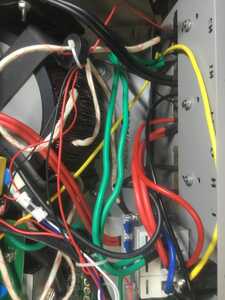
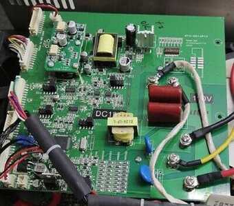
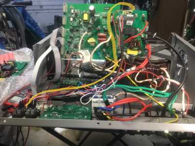
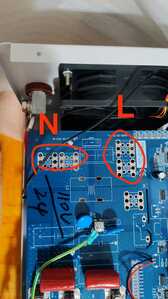
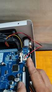
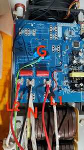
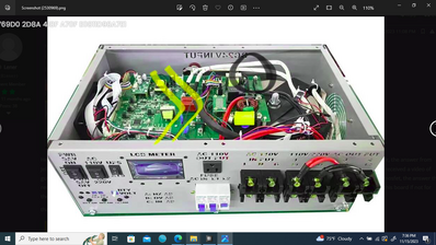
can anyone please tell me if this correct, looking at a picture (#2)from eBay power jack posting one of wire connectors look to be connected to a different location. The wire connector from the switch goes the charger picture (#1) for my unit picture however picture #2 eBay goes somewhere underneath the control board, the wires maybe different colors ( black and Red). I was wondering which one is correct yet where the is wire connects to Under the board.
Thank you for any help!
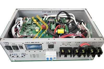
Ebay is correct . Your red wire is L1 . The other black wire in Ebay ptcture is N and go under the control board . Where is your sensor ribbon cable ? No connecter from the switch go to the charger board .
Just for hell of it trying to fix the inverter I ordered a replacement board and driver and 4 pieces of mosfets, I received a completely different looking board and of course Jelly ( if this a is really person) indicated this is new upgrade version but PJ has no tutorial/ instructions, I have absolutely no clue what to do… Jelly provides no help, already received about 22 files and pictures none have any relevant . Any ideas.?
thank you.
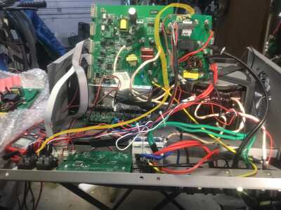
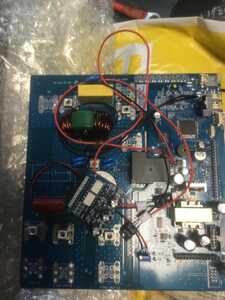
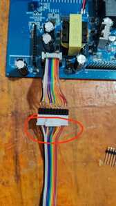
The first picture is the output charger board for a 20kw Powerjack inverter . Is that what the ebay seller sent you ? Is your inverter like the picture of the ebay inverter ? The picture of the ebay inverter with the 2 black circle is also a charger board but charging function do not work . The third picture is the control board that work with the output charger board in the first picture . I need to know if your original control board is rev 11.3 . I have all version of Powerjack inverter model and each is wired different . One wrong miss wire and the FETs will blowup .
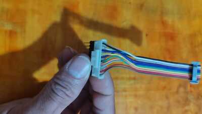
Here is the inverter 24v 12000w AGM sp, I have had about 25 or more emails back in forth with the same vendor that I purchased the inverter, the answer from Jelly always “kindly check again “ and sent me bunch of pictures but none related to the inverter absolutely no valuable instructions I actually received a video of guy playing with a current sensor and a stick of heat gun glue.I have sent numerous pictures parts numbers event the correct info from the mosfet, the answer the remaining the same “ kindly check again “amazingly those pictures below are the instructions. I do not know how to explain anymore to jelly this board if not for the 12000w inverter..
thank you.
