PLEASE NOTE: If you had an account with the previous forum, it has been ported to the new Genetry website!
You will need to reset the password to access the new forum. Click Log In → Forgot Password → enter your username or forum email address → click Email Reset Link.

Well>>>>> Sid did say or Sean (I forget) that they were working for PowerJack so it is likely that PowerJack uses whatever they choose as all is produced in PowerJack factories as I understand it from Sean's videos on YouTube. It seems that PowerJack is not adverising in the included brochures for Sean's Generry solar business anymore. I had received an inverter that had Sean's contact info with one or more powerjack inverters but now that information is ommitted from the newer inverters I have bought.
Before Sean was talking of a storefront to sell PowerJack inverters in partnere with PowerJack. have not heard much about that business venture in awhile on the YouTube videos.
Dickson???? How and where does your choke mount on the positive DC input? Is that outside the transformer case on the DC input cable?
organizing the off-grid solar power shed today in preparation of lifting the 96 plus pound 15,000 watt PSW LF PS PowerJack inverter into place. seems like I get a bit weaker with each passing year.😎
Todays rainy day project! the Lishen 272Ah 32 cell 4P8S 25.2 nominal volt battery is waiting for the inverter placement. cables are all made and ready. shelf is built and ready!
How and where does your choke mount on the positive DC input? Is that outside the transformer case on the DC input cable?
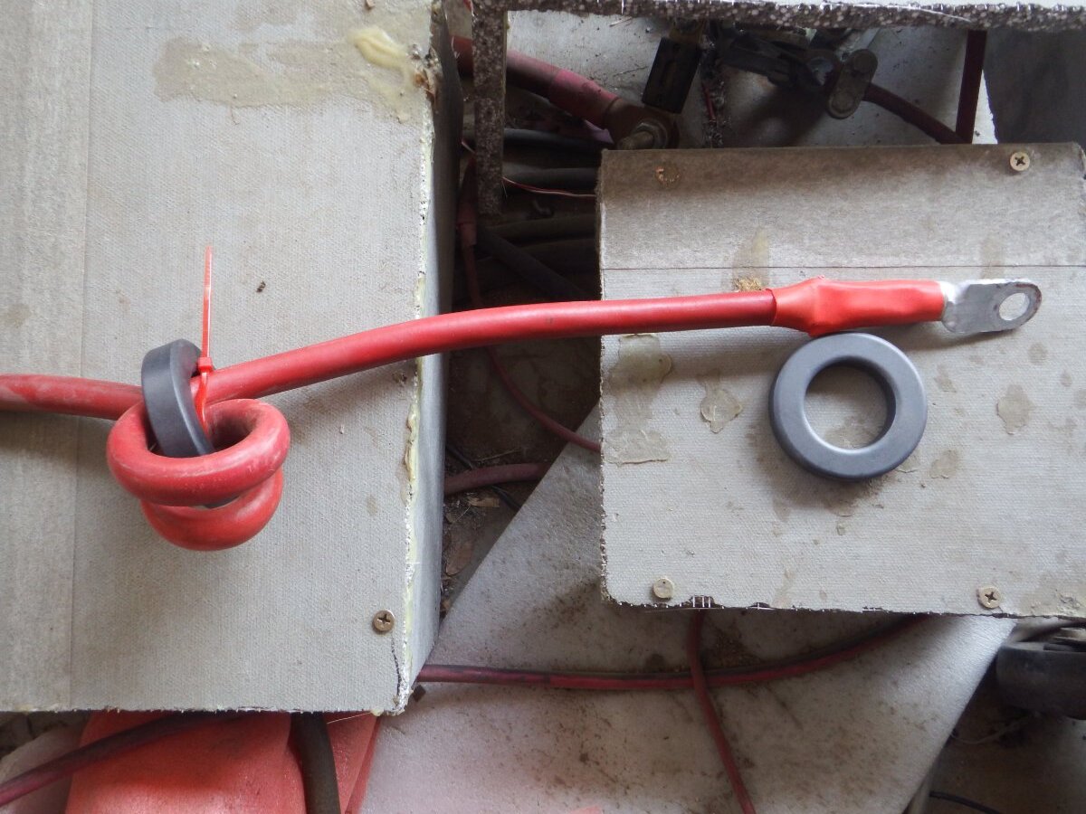
The choke suppose to be 40 uHenry but I copy what other inverter company give with their inverter to be loop one two or more times thru the 65mm ferrite core depend on wire size that fit . People on youtube say it do noting but I think it stop the voltage spike that back feed to the dc side when a inductive load switch on . I know the 10uF capacitor on L2 will stop the voltage spike on the AC side and help run the inductive load of the washing machine .
See the picture of the choke on positive cable . I put a choke on the negative cable also . A picture of a similar choke on ebay but not the same as mine .
.png.da9ace5289c79c0fab5d30ae691db112.png)
on "shematix" YouTube video he says that the choke does nothing on the dc side and only works on the ac side.
i am a bit more confused about the choke idea than before.
the idea of the choke is to lessen the flyback from surges on heavy loads, but that would be on the ac side or the ac output from the inverter ..... correct.
so many things to try to understand.
i did get the inverter up on the shelf yesterday but not much today as other things to do. i hooked up one of the inverter cables to the 400 amp class t fuse with 4/0 cable so small progress.
thanks for any help. still learning and trying to understand more....
maybe not talking about the exact same thing????
the idea of the choke is to lessen the flyback from surges on heavy loads, but that would be on the ac side or the ac output from the inverter ..... correct
Yes . If you open the transformer box there is a choke or 2 chokes on the AC side . I have 2 chokes outside the box on the DC pos and DC neg wires . When a heavy load like a heat pump start there is a huge surge on the AC side which cause a big drain on the DC side and the choke soften the huge inrush from the battery . People on youtube say DC choke do nothing which is true but nobody run a 4 ton heat pump on a powerjack either . I have to keep my battery voltage 61 volt to run inductive load that why I use the dangerous lithium ion electric car battery 16s . Those battery dump 300 amps in millisecond and the temperature of the transformer and moffet jump up fast .
maybe not talking about the exact same thing?
Another youtube by a electrical engineer EEVblog 1406 - DC Circuit Transients Fundamentals explain how bad an inductive load can be on the DC side . The battery DC input wire of the inverter go directly to the positive of the capacitor and the ripple on the capacitor will destroy the capacitor over time as mention in this forum . I put choke on the positive input like in the picture so now the circuit is a LC circuit . The choke will reduce the ripple on the capacitor and the capacitor will last a little longer running the heavy inductive load of the heat pump . The surge is so bad on the capacitor that the capacitor burn and the solder melted and the capacitor come loose . That why I need the 12kw GS next year . The DC choke also reduce the standby wattage to almost nothing .
i will study up on the chokes on ac and dc. thanks for your reply/guidance.
i suspect like you indicate and eevlog also at higher loads and voltages the transient spikes as the inverter ramps up and down may cause surge issues to the inverter electronics.
sounds like a good preventative way of giving it a soft start
i in time will see if i can aid the inverter a bit more to improve its performance.
today i am working on the Electrodacus SBMS0 hookup for the 32 cell Lishen LiFePO4 27,852.8Wh battery; I now have the heavy 15k 24-volt inverter on the shelf hooked to 4/0 cables now and to the 400 amp class T fuse.
thanks!
The surge is so bad on the capacitor that the capacitor burn and the solder melted and the capacitor come loose .
PJ had a rash of bad capacitors within the past year...caps that were poor quality and tended to fail easily. As far as I know those caps can be identified by their black label. PJ switched back to the beige/purplish caps after that, which haven't been problematic. Which color caps do your inverter have?
The DC choke also reduce the standby wattage to almost nothing .
What is the standby draw on your inverter now?
What is the standby draw on your inverter now?
DC positive cable measure 0.032 amp x 61v equal 1.95 watt . L2 has no filter cap measure 0.099 amp x 106v equal 10.49 watts . L1 has 4uf filter capacitor measure 0.002 amp x 116v equal 0.23 watt . The black label capacitors blew out were replaced with brown capacitors .
i will study up on the chokes on ac and dc. thanks for your reply/guidance
Powerjack now sell the largest choke I ever seem on ebay . 490 uHenry for the DC side and also can be put on the output AC side for L1 but maybe not L2 because has no filter capacitor . This make L1 like a surge protectin circuit .
The DC side will now be a LC filter circuit . see picture . Powerjack know their inverter has a problem and try the best to fix it . I just lately see that the Sol Ark and Growatt inverter has a major problem with surge but will be very difficult to fix because it is a HF Inverter . They has a difficult time running washing machine and dishwasher .
Here the pictures of the ebay inductor .
.png.860cb64c6e601d3b7f84625fbe2548e7.png)
.png.28b73fabc5d67ef1bfaaaac348899f8a.png)
.png.411d7b0065e7c76a0509d9ae23a15cb5.png)
.png.3df37b61b81d4138683459518ffd9ffc.png)
.png.b90349c3d8b58472fe9796d4a15282c4.png)
.png.6aec57ee25d4cf5af9551c3f8466a8ce.png)
DC positive cable measure 0.032 amp x 61v equal 1.95 watt . L2 has no filter cap measure 0.099 amp x 106v equal 10.49 watts .
I don't think your meter is reading DC amperage. With filtration, chokes, etc. you're getting the AC amperage down to a very commendable number--but that is not giving you the actual power draw of the inverter. For example, an AC clamp meter will read 0 amps with a straight resistive DC load (i.e. a heater) that's running 300A off a DC source.
You need to either use a DC shunt or a clamp ammeter that is capable of reading DC amperage. I personally have a Uni-T UT210E clamp meter, but there are other options available as well.
The magnetizing current of the main transformer is going to be somewhere above 25 watts. A fully "choked" and cleanly driven design may be able to run as low as ~0.6A @ 50v, or 30W.
I don't think your meter is reading DC amperage.
I have to measure with a different meter as reading is too low . Thank you . A year ago it was 0.4 a x 60v equal 24 watts .
I have to measure with a different meter as reading is too low
This morning I measure the pos DC cable is 0.171 amp x 62v equal 10.60 watt . I measure L2 is 0.099 amp x 106v equal 10.49 watt .
This morning I measure the pos DC cable is 0.171 amp x 62v equal 10.60 watt . I measure L2 is 0.099 amp x 106v equal 10.49 watt .
Yeah, you need a proper DC meter to calculate input wattage. 95% of the clamp meters will only register AC amperage--which you can get to extremely low levels with chokes and filtration. But an AC clamp meter cannot be used to determine overall system efficiency by "measuring power draw" on the DC battery cables.
As far as I know, DC clamp ammeters will have to be manually zeroed. If your meter auto-zeroes, it's an AC clamp meter.
There is no way that the switching losses + control board power requirements of your inverter are 0.11W. A whole "8kw" 24v PJ inverter runs 80mA @ 24v with just the electronics running (transformer off). That's 1.92W power draw WITHOUT the transformer or FETs in the picture.
- The LEDs on the MOS boards at idle state consume nearly 250mW (10mA @ 24v = 0.24W). If 48v, that's nearly 960mW (20mA @ 48v = 0.96W) loss with the entire inverter off.
- CPU alone is rated @ 100mW (0.1W), and it's fed by an LDO LM7805 regulator--which is a total loss device, requiring a total of 0.24W from the on-board 12v supply rail.
There is no way that the switching losses + control board power requirements of your inverter are 0.11W. A whole "8kw" 24v PJ inverter runs 80mA @ 24v with just the electronics running (transformer off).
The 4/0 positive cable is 11.0 watts on standby not 0.11 watt . The L2 output is 11.0 watts on the AC side awg 6 cable . This is the new measurement this morning . Last year was 24.0 watts .