PLEASE NOTE: If you had an account with the previous forum, it has been ported to the new Genetry website!
You will need to reset the password to access the new forum. Click Log In → Forgot Password → enter your username or forum email address → click Email Reset Link.
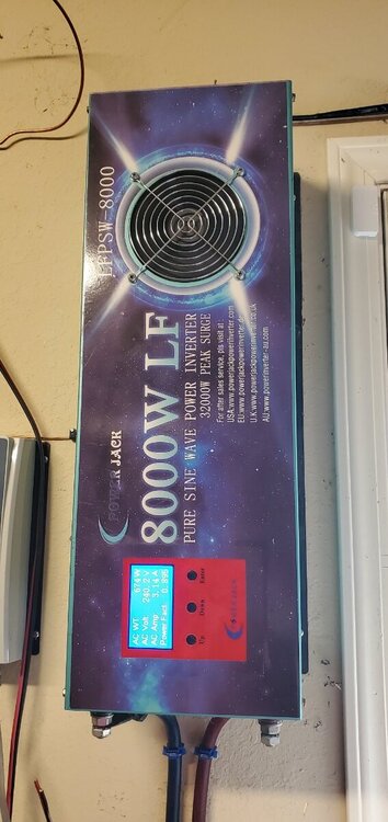
I have 2 Powerjack 8k LF Version 8 inverters. One popped when it was hooked to a/c charging circuit and it back fed the unit. My question is, can I combine the 2 coils and whatever necessary components from each in a new shell to make 1 larger, higher output inverter. And how would I go about that?
I have 2 Powerjack 8k LF Version 8 inverters. One popped when it was hooked to a/c charging circuit and it back fed the unit. My question is, can I combine the 2 coils and whatever necessary components from each in a new shell to make 1 larger, higher output inverter. And how would I go about that?
SORTA.
The only part you'll be able to "combine" would be the transformer itself.
OK, and maybe the mainboard (with the FETs on it) if your working inverter has 2 FET drive connectors on it (they're basically the same), sorta like PJ does with their bigger rated inverters.
Depends what parts you have. Definitely can't use 2 control boards.
Well, idea is to give me more capacity. Right now this 8k I'm running only gives me about 1300 on one leg before it goes into overload protect. Looking at the load imbalance it's typically only a few amps from l1 to l2. So if combining the coils will give me more load ability. I'm all about it...using it to power most of my house. Not overly heavy loads like microwaves or electric stoves. So loads typically fluctuate from l1 to l2 depending on what appliances are on
2 hours ago, Thatguydidit said:Well, idea is to give me more capacity. Right now this 8k I'm running only gives me about 1300 on one leg before it goes into overload protect. Looking at the load imbalance it's typically only a few amps from l1 to l2. So if combining the coils will give me more load ability. I'm all about it...using it to power most of my house. Not overly heavy loads like microwaves or electric stoves. So loads typically fluctuate from l1 to l2 depending on what appliances are on
So if it's going into OVERLOAD protect, that can be adjusted (depending on the control board version, there may be some DIP switches that set both the overload current + the charge current). OVERHEAT protection is different, and much more common (especially at the loads you're running, i.e. 2.6kw)...which doubling the transformers should help.
You could technically just parallel the 2 transformers across each other. WARNING: Make sure the transformer phases are the same, otherwise you're pretty much guaranteed to end up with blown FETs! To make sure the phase is correct, you can parallel what I call the "primary" (FET sides, PJ calls it "O/P"), and then parallel connect ONE of the "secondary" (PJ "I/P) 3 leads together. With the inverter running, use your DMM in AC volts to check across the other 2 pairs of leads, to verify that there is <5vAC difference between them. (If you see 480v or 240v difference, the transformer phases are definitely opposing! Swap either both of the "primary" wires, or try cross-color matching up "secondary" wires.) Do NOT under any circumstance connect "parallel" wires that have a voltage potential between them, or you'll risk smoked FETs.
If you encounter issues or questions, post here, and we'll sort it out.
And remember that any experimentations are at your own risk 😉. I can give pointers to accomplish what you might desire, but no guarantees come attached...
Well, idea is to give me more capacity.
You have the right idea. The transformer size is the key to capacity. If your two 8k units are identical, you should be ok to parallel the two transformers. As Sid says, make very sure your phases are correct or you will blow things up. You should be correct by matching colors of wires, but don't assume. Test!
You don't need the second mainboard/fets. You don't need anything but the extra transformer. If everything with the transformers paralleled goes as expected, the next step is to load it and see what happens. If you still get an overload at too low a load value, there is something else you can try. If your control board/output board has one of the 10 position dip switches (SW1) you may have to change some switch settings. As there appears to be no key to setting these correctly, you will have to experiment. The only thing known is that the higher the capacity of the inverter, the more of the switches are turned on. With the inverter off, try turning on one additional switch, then test again. Repeat until you get the capacity you should have, probably realistically you should be in the 3-4kw range, assuming you have enough cooling (very important!) for your transformers. Remember that setting the overload trigger to a higher value does not necessarily mean you are not overloading the inverter, so don't go any higher than necessary. Hopefully you have some way to monitor temperature of your transformer(s) because that is the real measure of your inverter's capacity. It has to run the load, and it has to do it without overheating. You will probably have to change to a high speed fan, or maybe add a second or third fan. One thing leads to another! Best of luck!
If your two 8k units are identical, you should be ok to parallel the two transformers
I read in another forum you have a powerjack inverter with 3 parallel transformers you bought in 2013 that is still working . Is this true ? Then you will know how it is done .
I read in another forum you have a powerjack inverter with 3 parallel transformers you bought in 2013 that is still working
I have two 2015 model 48v 15kw powerjacks that have three 2kw transformers each all in parallel. One still works and is currently running my house. I consider it much more reliable than the newer models because the transformers were better quality and the control boards before version 4 were more reliable and stable than the newer versions. Mainboards haven't changed too much. I also have a third 15kw that has two 3kw transformers in parallel. So yes I have proof that paralleling tranformers is possible and practical, provided the transformers are matched up very closely in all respects. Three 2kw transformers in parallel are effectively equal to one 6kw transformer. Yes, a 15kw powerjack is actually only a decent 6kw inverter, despite what their ads say. An 8kw inverter is actually a 3 to 4kw inverter depending on what transformer they came with.
Powerjack is constantly changing their suppliers so the parts in any two given inverters might be different. If <a data-ipshover="" data-ipshover-target="/profile/74-thatguydidit/?do=hovercard&referrer=https%253A%252F%252Fforums.genetrysolar.com%252Ftopic%252F202-combining-2-8kw-pjs-into-one-new-case-for-double-the-outputpossible%252F%253Ftab%253Dcomments" href="/profile/74-thatguydidit/" title="Go to Thatguydidit's profile" rel="">Thatguydidit bought his two 8k inverters at close to the same time, there's a fair chance his two transformers will match up properly for paralleling. He must be very careful in testing his transformers and his hookup to avoid loud noises and smoke. Some of powerjack's transformers have balanced L1 and L2 phases and some are unbalanced. My working 15kw has three unbalanced tranformers in parallel. That is, it puts out 120v on L1 to neutral and 110v on L2 to neutral. 230v L1 to L2. Needless to say, one could not parallel an unbalanced transformer with a balanced version.
My other 15kw inverter that currently needs a good control board has three balanced transformers. When it was working, L1 to neutral and L2 to neutral are each 115v. Still 230v L1 to L2. The 230v output is due to pre-version 4 control boards which all output 230v and were not adjustable. Later control board models dropped the output to 220v(why I don't know! - They should have increased output to 240v, not reduced it!). I would be thrilled to find an undamaged version 3.6a 230v control board, or even a v2.8. My two not-working inverters both had v2.2 control boards. I'm not a good enough tech to repair them, hence Non-Working. I'm always on the watch for an older 15kw multiple transformer inverter in good shape for sale. I know there were many sold for years. Where did they all go?
21 hours ago, dickson said:If your two 8k units are identical, you should be ok to parallel the two transformers
I read in another forum you have a powerjack inverter with 3 parallel transformers you bought in 2013 that is still working . Is this true ? Then you will know how it is done .
I think there must be another thatguydidit. The only other pj I ever got was a 3k in 2016.
I think there must be another thatguydidit. The only other pj I ever got was a 3k in 2016
Dochubert was the other guy in another forum . Trying to get 3 balanced transformer is like going down a rabbit hole . Way too expensive replacing FETS . It will be a lot cheaper to get a GS 12kw inverter and not have to replace FETS just testing spare parts I buy on ebay . One bad mosfet on one mosboard will destroy all the other mosfets and the LF driver and sometime the control board and the fire from the exploding FETS cause one of my mainboard to crack .
I think there must be another thatguydidit.
Well, then how are we ever going to figure out whodunnit? 🤪
My other 15kw inverter that currently needs a good control board has three balanced transformers post by dochubert .
Whodunnit is powerjack in 2013 to 2015 with 3 transformers . Maybe Sean has a control board from a donated inverter but probably not working also . Maybe a new rev11.1 control board will work . I use a rev11.1 control board to replace rev10.3 and also work to replace rev 9.0 control board .
I think there must be another thatguydidit. The only other pj I ever got was a 3k in 2016
Two people posting under the same username?
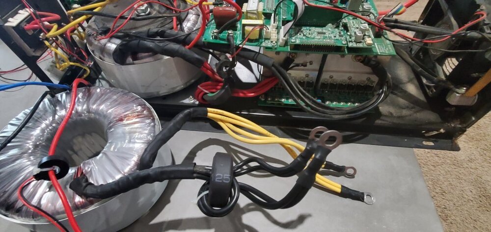
So I'm opening and getting started...looking at the 2 transformers they are dated a month apart, but wire color is different...am I to assume that the ferrite ring on both sets would be a safe way to assume input? The windings on the working transformer are black n red, with the red being the outside winding run through the ferrite. The transformer I want to wire in has black n yellow with the inside winding which is black run through the ferrite, so it's opposite
pj.thumb.png.4b28b96b3ca6d9e9c6408110a7065266.png)
pj.thumb.png.1d66f18f5c815818db4ad78e3d32b833.png)
pj.thumb.png.d1c23929073166a15359be768dab050f.png)


