PLEASE NOTE: If you had an account with the previous forum, it has been ported to the new Genetry website!
You will need to reset the password to access the new forum. Click Log In → Forgot Password → enter your username or forum email address → click Email Reset Link.
I have a 48v 15000 watt power jack inverter/ charger that was working good til the battery voltage dropped down to 44 volts and then it shut down. I switched over to utility comp power til battery voltage was brought up to 52v. I tried to restart the inverter but the when turning power on the red alarm light comes on and stays on but no auditable alarm noise only red light. I tried draining the power from the inverter completely and powering it back on but still no go. The led screen on inverter powers up but the inverter does nothing.
Thanks
Sam
Also I wanted to add the 2 green light are on when I power inverter up as well
And the dip switch seems to be acting funny. I have open lead acid battery and I'm suppose to have it on setting 6 but one of the green lights isn't that bright as apposed to having it on 5. I've always had issues with the fan always running also
If all 3 LEDs are lighting up, this means that the CPU is stuck in startup. Possible that it's resetting dozens of times per second due to shorted FETs or otherwise?
One way to check if the FETs are at fault would be to unscrew and unplug the LF Driver board. If the inverter gives a beep error (and just the red light), that'd kinda indicate FETs are damaged.
Charge / AC input on PJ inverters seems to be a bit problematic. No comment on that 😉.
And the dip switch seems to be acting funny. I have open lead acid battery and I'm suppose to have it on setting 6 but one of the green lights isn't that bright as apposed to having it on 5. I've always had issues with the fan always running also
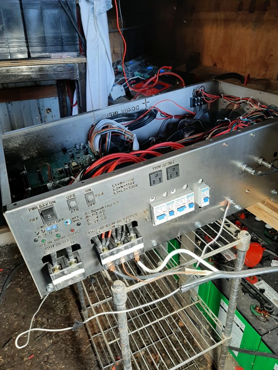
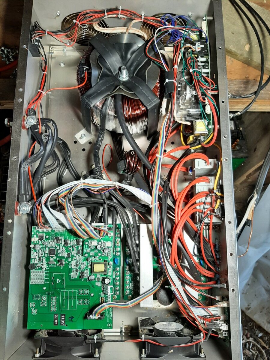
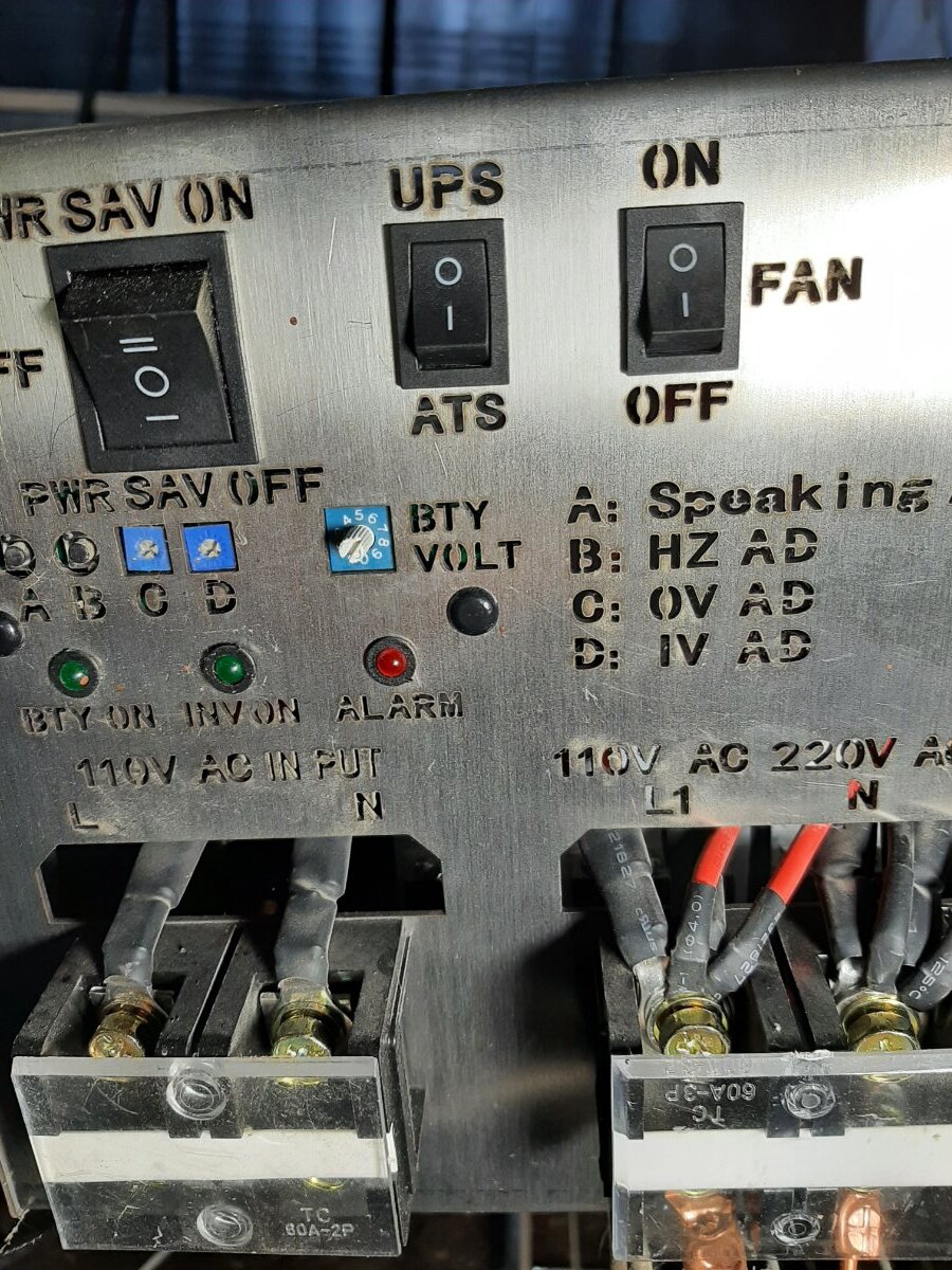
Is the dip switch inside the inverter ? My 15kw PS fan run even after shut down for an hour which is normal because sometimes it takes the transformer 2 hours to cool down . Your 15kw can be repair but without charging function if that is ok ? The information given so far do not tell what parts are needed except that it is not working . I need photo of control board and charger and output board that show L! and neutral from transformer wire connections . What is the voltage from transformer L1 to N and L2 to N after removing the cover ? Measuring ac voltage is very dangerous so if you never done electronic work then maybe just take some photos to see if parts is still available . Thank you .
If all 3 LEDs are lighting up, this means that the CPU is stuck in startup. Possible that it's resetting dozens of times per second due to shorted FETs or otherwise?
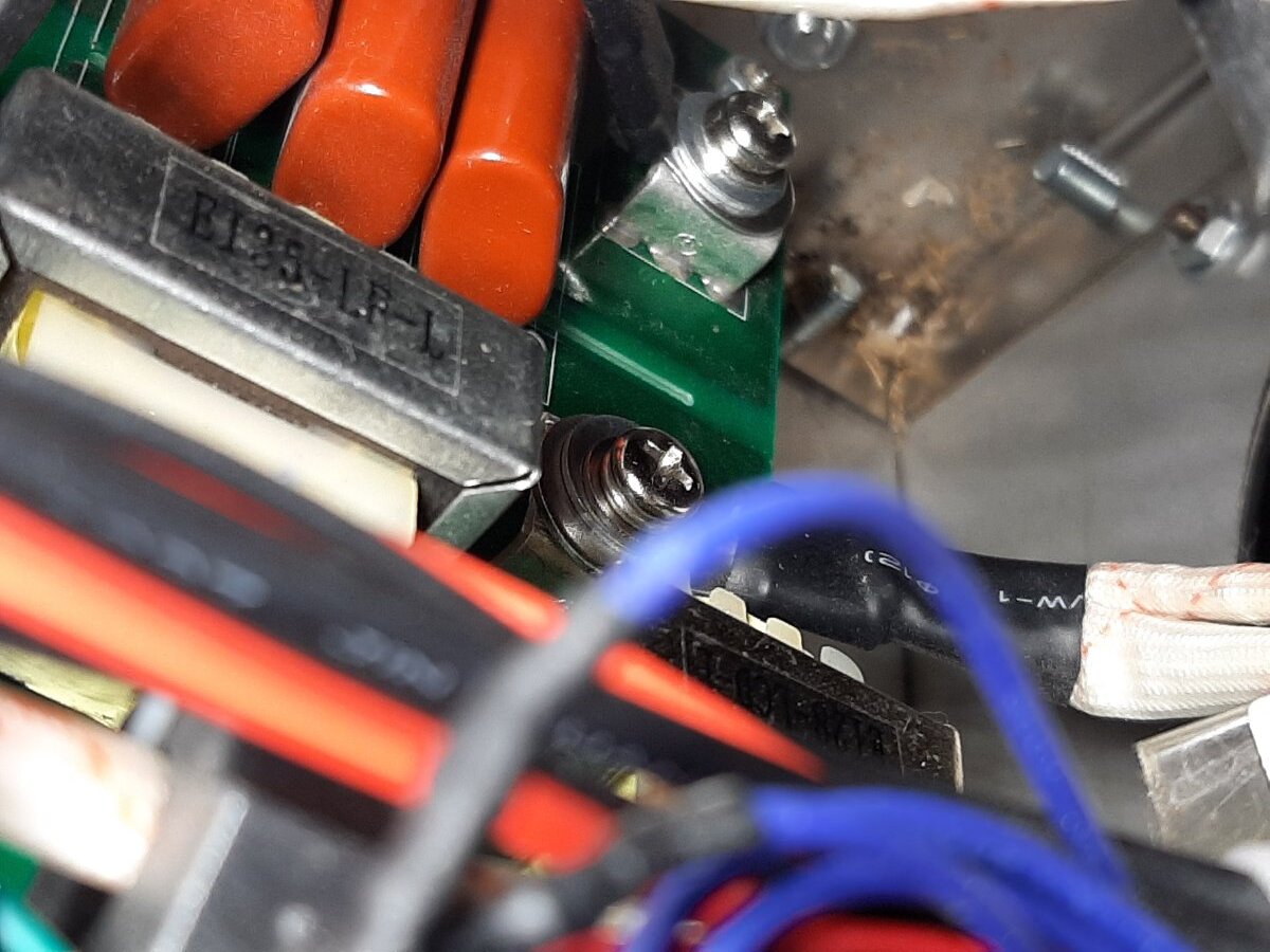
Ty for input. What 3 led lights are you referring to? Please look at pics and let me know what you think. Also when inverter shut down over low voltage I shut inverter off within 2 min. I never smelled anything burnt. I checked voltage of black wires going from the Moffett heat sink to transformer and its reading direct voltage/ 28 volts on each heat sink. I checked for ac voltage coming out of inverter and there is no voltage reading.


And the dip switch seems to be acting funny. I have open lead acid battery and I'm suppose to have it on setting 6 but one of the green lights isn't that bright as apposed to having it on 5. I've always had issues with the fan always running also
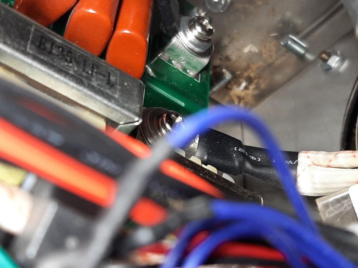
I was mistaken when speaking abt dip switch. I mentioned to say selector switch. Also when measuring voltage from heat sink to transformer I get a reading of 28v direct current on each heat sink which together equal battery voltage. The white insulated wires coming out of transformer measure 0 voltage. Please look at pics and get back with me.
Ty


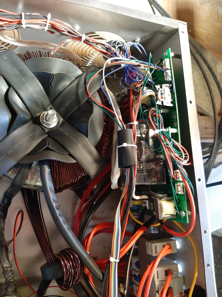
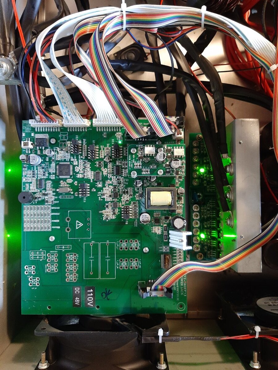


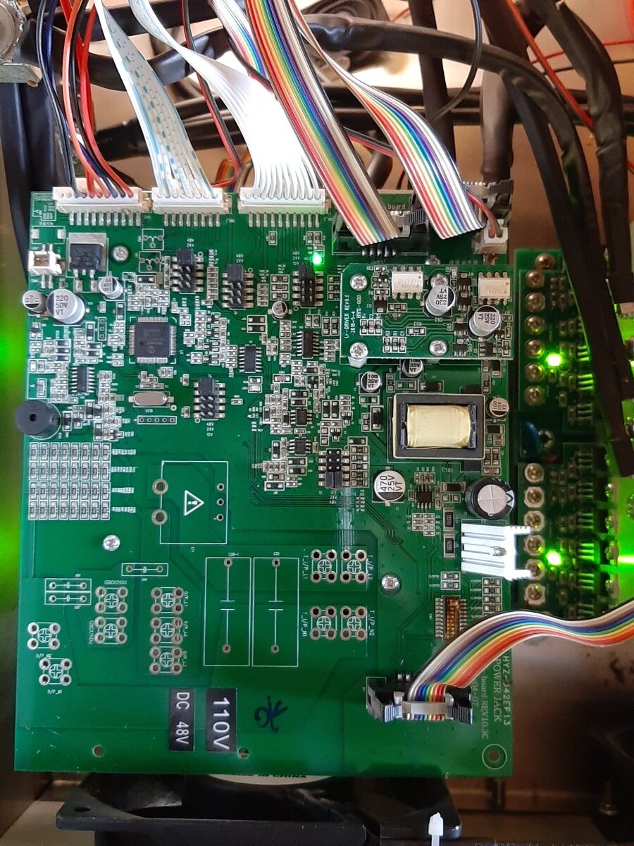
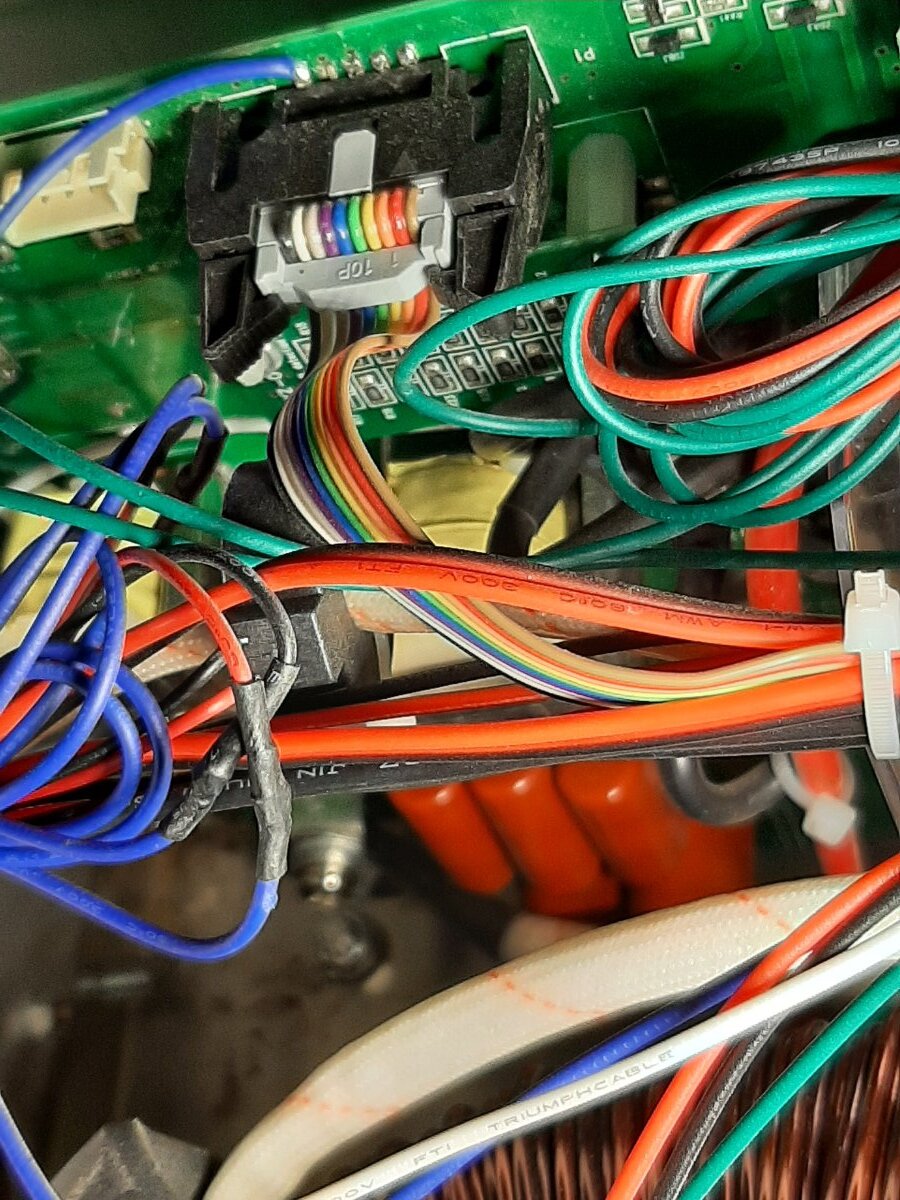
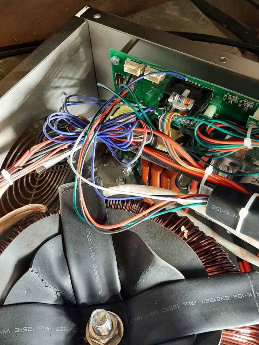
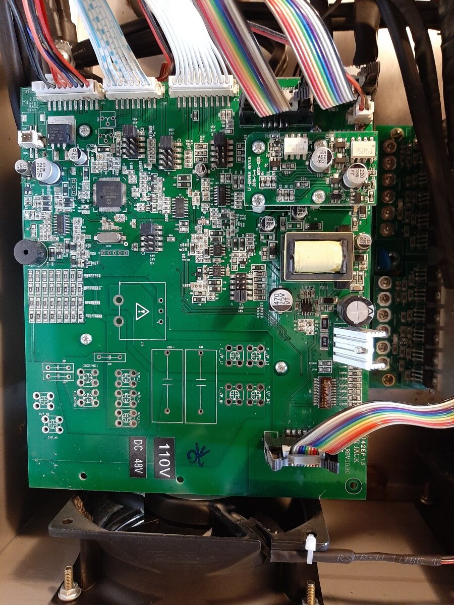
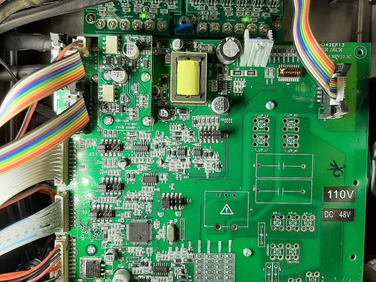
Thank you for the sharp photos . The white wires reading zero at the transformer mean the LF driver not working . I see one led light up on control board and no led light up on LF driver . Is this photo taken with the switch on ? The control board should have 3 led on continuous and LF driver led on also when switch on . Mosfets are all good from the photos . Please turn switch on for no more than 5 seconds to see if the 3 leds on control board start blinking and one LF driver led also blink . IF any led is blinking SHUT OFF the switch immediately or the mofets may blow up . Let me know .
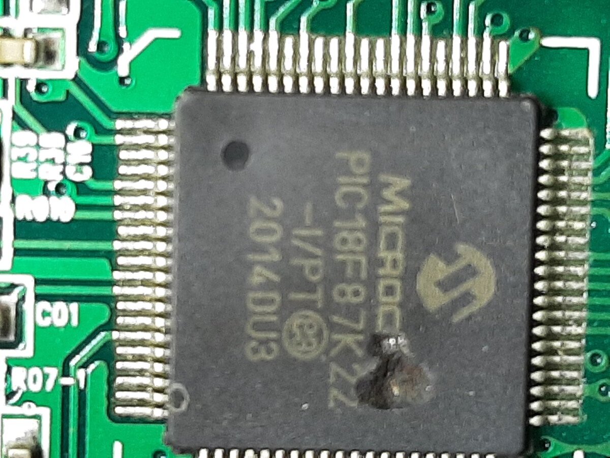
@samI'm afraid you spotted the problem....that hole in the main MCU ("CPU" PJ calls it) shouldn't be there--it indicates catastrophic failure of the MCU (microcontroller unit). Wish I knew what the MCU die looked like, that way I could use some forensic analysis to determine what caused it to blow...
You'll need at least a new control board. Not sure if the damage has gone any farther downstream (i.e. LF Driver / MOS boards)...
<fileStore.core_Attachment>/monthly_2021_07/image.png.cb27f2307bcf00e9e1b96750c81f0a7d.png
Looked at the pinout...technically, the only signal line that could cause issues in that area of the "CPU" is the AC Mains relay. Wonder if it doesn't have a sufficient backsplash diode on it...?
The same port that controls the relay also controls all 3 LEDs (front panel).
The same port that controls the relay also controls all 3 LEDs (front panel).
Yes sir . The new rev 11.1 control board come with new LF driver will fix your inverter . The mosboard led is on may not mean the mosboard is good . All the mosfets need to be check like in Sean video and I found that the last shipment of mosboard has some bad resistor . A bad resistor on one mosboard will blow up all the other mosfets that I test on my test bench . You can not trust ebay parts . Show the photos of the bad MCU and your test of the transformer ac voltage is zero and some of the other photos and do not comment on charger and that your max load is less than 5000w and the seller may send the parts or the spare parts is 100 dollars . Ask for the output board since your voltage reading is zero . Thank you .
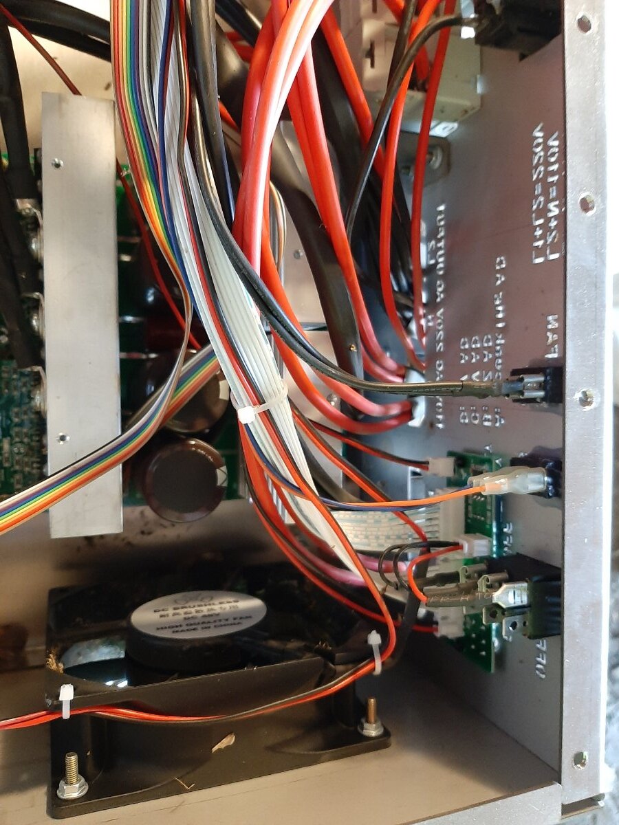
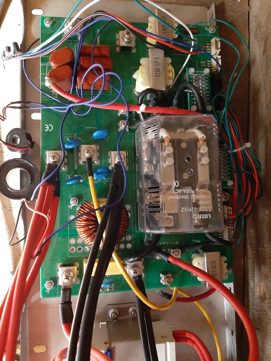
Im still having troubles with this inverter. I contacted supplier I purchased it from and they gave me 2 new cpu boards and drivers and still it does not work. I check the wires coming off transformer into AC board and they are tight. I measured the voltage coming out of transformer and the pic with the blue circles measure roughly 115v but the one wire in bottom left of that pick right above the blue circle has no voltage on it. This has the battery charger on this but if I can bypass that in anyway to resolve this issue Im all for it.
thanks
sam
<a href="/monthly_2021_09/Inked20210913_194301_LI.jpg.e640f07dae3d2ba072c1687d3253b499.jpg" class="ipsAttachLink ipsAttachLink_image"><img data-fileid="717" src="//forums.genetrysolar.com/applications/core/interface/js/spacer.png" data-src="/monthly_2021_09/Inked20210913_194301_LI.thumb.jpg.2dc8f07cd354832f25fbc01c48ce7ccb.jpg" data-ratio="133.45" width="562" class="ipsImage ipsImage_thumbnailed" alt="Inked20210913_194301_LI.jpg">
I contacted supplier I purchased it from and they gave me 2 new cpu boards and drivers and still it does not work
I go back to your post on july 28 . Look like you replace the rev 10.3 control board with the bad MCU with a new rev 11.1 control board . Your new picture show the green LED working but has problem . Your output and charger board show 115 vac . My 15kw powerjack do not have charger board and is wire different . I will open my powerjack and get back to this post later . Your charger board may be damage on july 28 and need to be change with a output board that has no charger board . Thank you for the video and I will compare to my rev 11.1 control board running with no problem later .
also i disassembled the inverter a little more so I could test mosfets. I got 1 section removed and it tested great. The visual inspection shows no signs of bad mosfets. I took a picture of what I believe is the ac charge board and probably the direct current charger. I dont understand how to hook up the charger. From what I understand I should wire up 110 volts to the 110 input on the front lower left panel of inverter but the thing is I have 110v going out of it. Not shur why? I attached a pic of the front cover where the 110 input is and I circled it in blue but I have 110 coming out.
thanks
sam

I dont understand how to hook up the charger. From what I understand I should wire up 110 volts to the 110 input on the front lower left panel of inverter
Sorry my 15kw do not have a charger board and I do not know how to hook up the charger . Can you not connect to the 110 input and not use charging ? Almost eveyone who post in this forum say charging is a problem . Your connection to the L1 N L2 output is disturbing . The bare copper wire is Ground and suppose connect to the inverter metal case . The white wire is N to the inverter output and need to be AWG 6 the same size as the red and black to L1 and L2 . My output board which has no charging is completely different from your output board in the picture . There is not and easy way to modify your inverter with an output board like mine . I suggest send the video of the LED blinking and making the thumping noise to the seller and have a powerjack engineer look at the video . Thank you for all the pictures . Now I know why Sean have such a hard time repairing powerjack inverter and not answer because of all the diiferent boards .