PLEASE NOTE: If you had an account with the previous forum, it has been ported to the new Genetry website!
You will need to reset the password to access the new forum. Click Log In → Forgot Password → enter your username or forum email address → click Email Reset Link.
Hello everyone,
I'm running my Powerjack 8KW LF inverter for almost 6 years now without any big problem. This said, I got new appliances who are sensitive to the frequency that my inverter generates (50hz at the moment).
Anyone here found and adjustment screw on the main board to tweak the generated frequency from 50hz to 60hz?
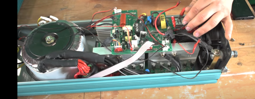
Unfortunately, I do not have the model revision number. Here are pictures of my actual model:
Hope someone can give me a hand on this.
Thanks!!
Felix
Looks like you got an oldie there--and the old ones just seem to keep running.
Frequency is determined by the "CPU" (it's an MCU, but I digress!) Control boards with the Microchip CPU have frequency adjust with a button (switching between the 2). I can't tell for sure, but I'm guessing on that inverter, you'll need @dochubert to chime in.
What's the control board version on that inverter?
Thank you for this nice answer. Much appreciated. Where exactly can I find the board revision number? On the board itself?
Yes, it should be printed on the board somewhere. "LF BOARD REV[xxx]"
Hi Felix,
You're control board revision number will be right next to the black relay that has a 'DC 12v' sticker on it. Looks like a v3.4 to me (guessing). Sorry but there is no adjustment to change frequency on the older control boards like yours.
If it uses the Microchip PIC main processor, I am relatively confident we should be able to get it to run 60Hz...though it may take tracing pins on the CPU to connectors to find the required pins for the frequency adjust button. (If it uses the older Motorola/Freescale processor, you might be out of luck though.)
@felixWhat we need to know is the control board version number and/or just a better closeup of the PCB (we can read the number right off it then / check CPU manufacturer). Once we know what version control board it is, I might even be able to ask Sean for info.
I looked through some forums' posts but found nobody had converted an older powerjack from 50hz to 60hz.
That said, since powerjack made both versions, the control board should have someplace to make the choice. A solder pad or a resistor that gets removed. Looking at an old v2.2 control board I saw a solder pad labeled "Adjust" next to connector CN4 on the transformer end of the board. There is a resistor soldered to it that reads 13 ohms with my meter. Note that <a class="ipsAttachLink ipsAttachLink_image" href="/monthly_2021_11/420599252_Adjustsolderpad.jpg.9a214b9c27494fd76f9f80626033e8dd.jpg" data-fileid="906" data-fileext="jpg" rel=""><img class="ipsImage ipsImage_thumbnailed" data-fileid="906" data-ratio="133.45" width="562" alt="942537652_Adjustsolderpad.thumb.jpg.0684255f35d36bd3a75320337145c13c.jpg" data-src="/monthly_2021_11/942537652_Adjustsolderpad.thumb.jpg.0684255f35d36bd3a75320337145c13c.jpg" src="/applications/core/interface/js/spacer.png" /> control board has nothing connected to it. No power, transformer, or other connections. Readings with anything connected could change the value of the reading in ohms. Caution! Take no ohm readings with ANY power source connected!
Felix, if your 50hz control board has either nothing (open connection) or some value different from 13 ohms across the Adjust solder pad, we may have our selection point.
Please check and let us know.
3 hours ago, dochubert said:Looking at an old v2.2 control board I saw a solder pad labeled "Adjust" next to connector CN4 on the transformer end of the board. There is a resistor soldered to it that reads 13 ohms with my meter.
Any chance this has something to do with the battery charge current / overload protection (one and the same, heh heh)? Up until v9, they would adjust the resistors on the board; at v9+ they added a small SMT "DIP" switch to make it easier to adjust the "gain" of the current feedback circuitry.
The resistor's placement next to a 2-pin connector AND an LM358 makes it look more like a current sense transformer load resistor.
The resistor's placement next to a 2-pin connector AND an LM358 makes it look more like a current sense transformer load resistor.
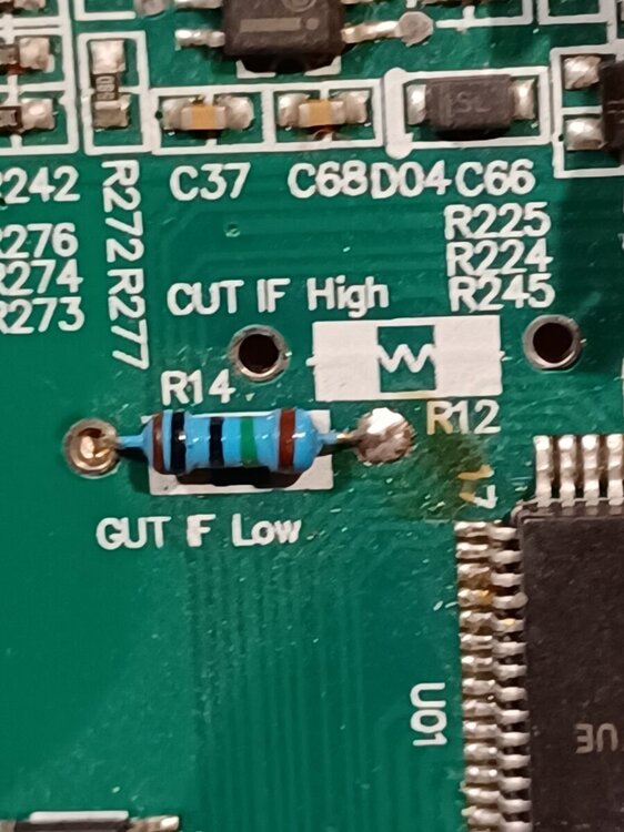
I'm sure you are probably correct. I'm just trying to find something likely, as there should be something for the frequency selection. Actually just found something else. Check this pic of r14 and r12. Below r14 it says "cut if low" My 60hz board has no r12 resistor. Above r12 it says "cut if high". If Felix's board has a resistor in r12 but none in r14 that might explain it. What do you think?
The left sides of r12 and r14 are common and the right sides go to different pins on the processor. Seems to support the theory.
I definitely concur that this could very well be a frequency adjustment 😉.
So now we wait for Felix to let us know if his control board has an r12 resistor or an r14 resistor. Or anybody else with an older 50hz powerjack using a control board older than v4 could give us the same info. Sean might know if he has worked on any 50hz older boards.
Guys the inverter is at a remote location. Really sorry for this long delay. So here is pictures of the inside (I know it's dusty...).
Hope you will find the info (rev) that you are looking for. It says "HCJ v2.2" close to the Power Mosfets modules...
With the picture that you see, is it possible to tweak it from50hz to 60hz?
//content.invisioncic.com/g308908/monthly_2021_12/20211210_110819.thumb.jpg.444f48d849c20697d382b70e96debafe.jpg
//content.invisioncic.com/g308908/monthly_2021_12/20211210_110829.thumb.jpg.cc943aa8885c2025847cdb53ee26a645.jpg
//content.invisioncic.com/g308908/monthly_2021_12/20211210_110839.thumb.jpg.0c30c4f1f2161302e088a281df78a658.jpg
//content.invisioncic.com/g308908/monthly_2021_12/20211210_110845.thumb.jpg.0180924d661ede9592ea305b1ff97c09.jpg
//content.invisioncic.com/g308908/monthly_2021_12/20211210_110850.thumb.jpg.6a344afb92002b9465bbbe7427a6ff42.jpg
//content.invisioncic.com/g308908/monthly_2021_12/20211210_110931.thumb.jpg.3c9461b08fe89dc98ac4190f5411b96c.jpg
//content.invisioncic.com/g308908/monthly_2021_12/20211210_110937.thumb.jpg.0143a47b2fdc5509b183f85aa4b6adc3.jpg
//content.invisioncic.com/g308908/monthly_2021_12/20211210_110947.thumb.jpg.f260ae6d38177b870eb769be99bd4557.jpg
//content.invisioncic.com/g308908/monthly_2021_12/20211210_110951.thumb.jpg.d252c33498801e747959009dbfa4c418.jpg
@dochubert Here is what I've found (picture below). Seems the same board as yours.
And I think it contains the fix of my situation. Should I just desolder the R14 "low F" resistor and resold it to the R12 "high F" holes?
I think it could do the trick. What do you think?
Definitely the older boards with the older CPU 😉
My unofficial conclusion: yes, try moving the resistor from the "F Low" to the "F High"...see what happens.


![20211210_113032[1].jpg](/wp-content/uploads/wpforo/default_attachments/IPB/s3_g308908/monthly_2021_12/1124746001_20211210_1130321.thumb.jpg.ad71cbf395d77039001055d812e18488.jpg)