PLEASE NOTE: If you had an account with the previous forum, it has been ported to the new Genetry website!
You will need to reset the password to access the new forum. Click Log In → Forgot Password → enter your username or forum email address → click Email Reset Link.
"
9 hours ago, Sid Genetry Solar said:Definitely the older boards with the older CPU 😉
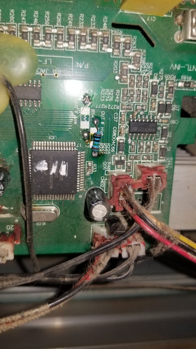
My unofficial conclusion: yes, try moving the resistor from the "F Low" to the "F High"...see what happens.
See what happens sounds dangerous 😂
This said, let me give it a shot and let you know.
"
Understood, haha.
Big problem is that this board is old enough that it uses the older processor, which I know next to nothing about. I can answer just about any pertinent question on PJ inverters using the Microchip CPU, though.
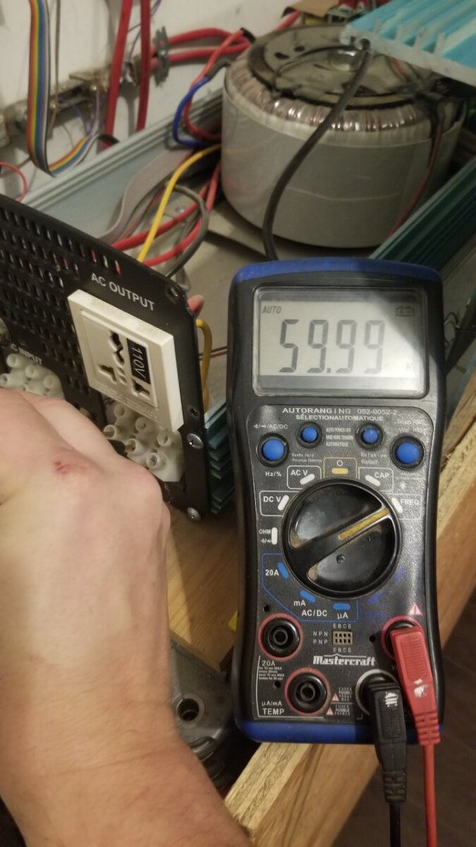
Seems to work!
Also, the charging system now works on 60hz.
Thanks to all!
I guess you CAN teach an old PJ some new tricks 😉
Guesses were a stab in the dark, but it looks like it worked.
Strange though, that resistor (if I'm reading it correctly) is a 10Mohm resistor. Very high resistance.

Well, I'm more confused than ever now. All of my older 60hz control boards had the resistor at r14 and nothing at r12. Felix, moving yours to r12 should have changed it from 60hz to 50hz, not the other way around. I was speculating that yours originally had the resistor at r12 and you would be moving it to r14. Why it did what you wanted, I have no idea. Hope it continues to work for you, but I would definitely keep an eye on it.
If there was ever anything consistent about powerjack inverters, it is that they are never consistent.
that resistor (if I'm reading it correctly) is a 10Mohm resistor.
That is correct. 10 Mohms. That resistor was key to high dc voltage trips also. When battery voltage (like mine at that time) hovered around 58v, inadvertant high dc voltage trips happened at times. Very annoying. Some folks put a zener diode across it to stop high dc voltage trips entirely. I changed the 10Mohm to 7.5Mohm on mine, which bumped the trip point up a couple of volts, solving the problem without completely defeating the high voltage trip safety feature.
<a contenteditable="false" data-ipshover="" data-ipshover-target="/profile/2-sid-genetry-solar/?do=hovercard" data-mentionid="2" href="/profile/2-sid-genetry-solar/" rel="">@Sid Genetry Solar <a contenteditable="false" data-ipshover="" data-ipshover-target="/profile/6-dochubert/?do=hovercard" data-mentionid="6" href="/profile/6-dochubert/" rel="">@dochubert
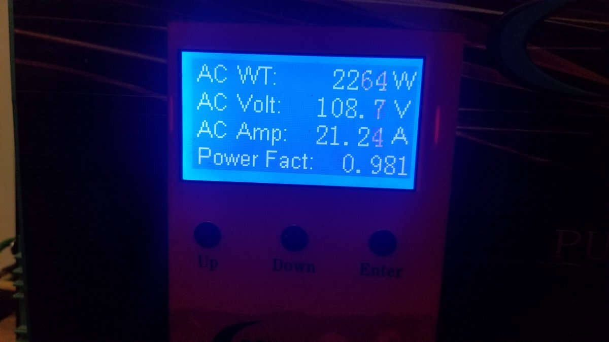
Just want to let you know that it is still working fine on 60hz 🙂
Now here is my next challenge: Increasing from 110v to 120v. Anyone as an idea of a starting point where to look for on this old model?
Again, thank you very much for such valuable inputs! 👍
Increasing from 110v to 120v.
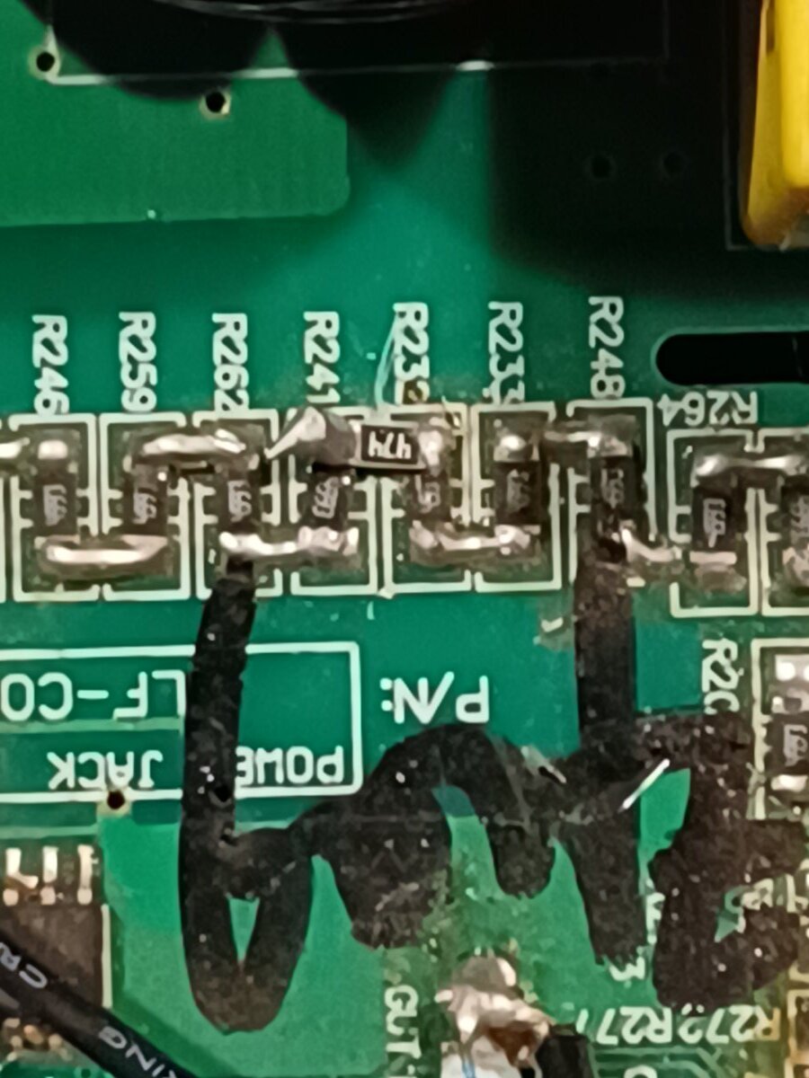
Sadly, there was no set place or way to easily adjust output voltage on these older control boards. That said, a friend I made on another forum years ago suggested adding a resistor to the series resistor ladder (see pic). You open/scrape the trace between two of the resistors in the ladder, then solder in a resistor of approximately the same value as the others across the open trace you just made. This adds one more resistor in series to the ladder. The pic is from my own 230v control board, and it succesfully raised output voltage to approximately 240v. The resistor ladder is not different on a 110v control board so the same scheme should work to raise 110v to 120v. Be aware that some of these 110v boards were actually 115v boards, so you could get higher than 120v. Possibly 125v. Test before loading!
You try this at your own risk. I make no guarantees, especially if you are talking about a 110v board, which I never tried to modify. If you find that voltage is too high, you could always try a different value resistor, say half the value of your first try.
Good luck and hope it works for you. Glad to hear also that the conversion to 60hz is still doing good.
@dochubert You're the best. Let me give it a try and come back to you about it. Thanks again!
Taking another look at my sloppy soldering, as well as powerjack's sloppy soldering, it's a wonder anything worked!
Reminds me of the question I never got an answer to years ago when this was going on. Why a resistor ladder anyway? Why not just put one resistor of the total resistance of the series string in and forget the complications of having all those resistors to buy and solder in? Never made any sense to me....
And look at the numbering! They're in series but numbered 248, 233, 232, 241, 262, 259, 246, 247, 260, 261, and 240. And the other ladders' numbering is just as screwy. Another screwy powerjack standard I guess!
a variable resistor there would give you some adjustment.
Reminds me of the question I never got an answer to years ago when this was going on. Why a resistor ladder anyway? Why not just put one resistor of the total resistance of the series string in and forget the complications of having all those resistors to buy and solder in? Never made any sense to me....
There is some reasoning to the madness there. Personally, I do not like the long resistor string method (notice that most of them are "4993" or 4.99Mohm each), but it does sorta work.
The reason for the high resistance is that this huge long string of resistors is the only form of "isolation" for the AC feedback signals (AC Input and AC Output). I suppose if you get 50MOhm of resistance, that's technically considered a remote sort of isolation...but I've always wondered about how much the differential voltage potential across the string affects the actual output reading (i.e. shorting L1 or L2 to battery positive or negative). Didn't seem to affect it in my testing, but I do know that the use of such a high impedance signal greatly increases the potential for noise and unexpected behavior. (In the case of PJ inverters, the high/low feedback waves start to diverge under increased load.)
The reason for the large number of resistors CAN in some cases be to increase power dissipation. This is why the GS boards have (albeit a much smaller) strings of resistors on the AC side of the isolation devices.
However, in the case of the PJ and other Chinese LF inverter boards, the long resistor strings are necessary due to the comparatively low voltage rating of a SMD resistors. An 0603 resistor is usually rated at 50v max (regardless of the resistance). Putting multiple resistors in series effectively increases the total voltage rating of the string--which if you want to have 500v "isolation potential" from either measured line, that's 10 resistors per side (20pcs total).
EDIT: PJ uses mostly 0805 SMD resistors/caps, which are usually rated to 75v. Still...as these are also the isolation barrier, it takes quite a few of them in series to get any significant voltage rating. This is why on the older boards they're also put end-to-end; the newer PJ boards bunch 'em all up, completely forgetting the reason why there's so many in the first place!
And look at the numbering! They're in series but numbered 248, 233, 232, 241, 262, 259, 246, 247, 260, 261, and 240. And the other ladders' numbering is just as screwy. Another screwy powerjack standard I guess!
In KiCad (which I use...PJ doesn't) the automatic "annotation" goes by X-Y priority--and I usually don't care to number parts myself. This results in some very wonky numbering schemas--and most of the time, illogical numbering is completely ignored. I know I don't pay too much attention to it....
It worked ! 1M ohms did the trick. Thanks again for the support !
Isolation is a big part of it. If one resistor fails short and that's all there is in the circuit something is not going to have a good day. With multiple in series if one fails short the readings will go whacky, but nothing on the low voltage end of the string will let the smoke out. The resistor doesn't even need to fail, creepage comes into play too.
It's pretty usual for decent quality test equipment to have strings of resistors when high voltages have to be reduced. Lots of other circumstances too, medical gear etc.
Thanks for the explanations Sid and Butcher. Makes sense now.
Felix, glad the mod worked for you. What output voltage did you end up with?
@dochubert It worked! I added a 1M ohms resistor, and it did the trick. Now I have a fullly converter 120v@60hz inverter.
Thanks again for your valuable insights.