PLEASE NOTE: If you had an account with the previous forum, it has been ported to the new Genetry website!
You will need to reset the password to access the new forum. Click Log In → Forgot Password → enter your username or forum email address → click Email Reset Link.
i have not done this with the top cover off, so i cant speak to the internal heat.
After an overload shutdown, you can turn the inverter off, and remove the cover to feel for heat; especially with no fan running, it'll take a few minutes to cool down.
I just checked the 11.1 board and found that the DID run the fan positive line all the way to the battery positive (through the very thin FET cables). So the fan SHOULD be getting 24v (not 12v as in all prior versions.) EDIT: that means there's no need to cut/splice battery positive to the fan positive lead.
Making matters doubly worse is the completely inexplicable fan connector design. There's 2 connectors...and THEY'RE BOTH OPPOSITE POLARITY from each other!
In other words, plugging the fan into one connector might work fine. Plugging it into the other connector will reverse-bias it. Best case, it just won't run; worst case, it'll blow the fan out and/or melt inverter wiring, etc. Saving grace here might be that the FET is barely turned on in the first place.......!
Your best bet here is to match up the fan polarity (red/black) with the connector that has the corresponding proper polarity.

Once you're sure the fan is plugged into the correct polarity port, then you can continue testing:
- experiment bypassing the MOSFET (with battery connected, but the inverter does not have to be running).

When you short the 2 leads out, the fan should run.
If it doesn't, there's a power/wiring issue to the fan.
- If the inverter did an overheat shutdown, it's prime time for a measurement with a voltmeter (digital preferred!) You have to be careful with this one...as shorting this FET lead to the adjacent one will likely blow the FET (and possibly the CPU). With the inverter ON and complaining about overheat, measure the voltage from the gate of the MOSFET to battery negative (note: only positive meter probe shown here):

If this is 0v, then the CPU isn't even turning the MOSFET on.
If it is close to 5v, then we have a MOSFET issue.
OK, so when i shorted the FET, the fan did turn on, but the next problem i am experiencing is trying to heat up the inverter, it seems that a couple car batteries borrowed for testing do not have enough juice to run a space heater. I guess I will have to use my main battery bank.
So it turned out that it was just a loose connection between the fan male plug and the board female socket, how annoying. thank you so much for your help.
Also, are you someone i can buy replacement PJ parts from?
Thank you again,
Kyle
Also, are you someone i can buy replacement PJ parts from?
Not me, but @sean-genetry-solar has SOME replacement parts (all older, none of the new v11 stuff AFAIK). Don't think he's gotten any new replacement parts from PJ though; you probably are totally at the mercy of PJ as to whether you can buy replacement parts.

Hi Kyle,
I figured out some years ago that it was much easier (and more reliable) to just go around powerjack's flaky fan controls. Even when they work they turn on the fan at unpredictable times and frequently much higher inverter temps than I wanted. (The sooner your fan turns on, the less heating your inverter endures, and therefore the longer it will last - my theory anyway!)
To that end I don't interfere with powerjack's fan controls. Instead I add two of these:
https://www.ebay.com/itm/194245273137?hash=item2d39eba631:g:1lgAAOSwHONg8tW-
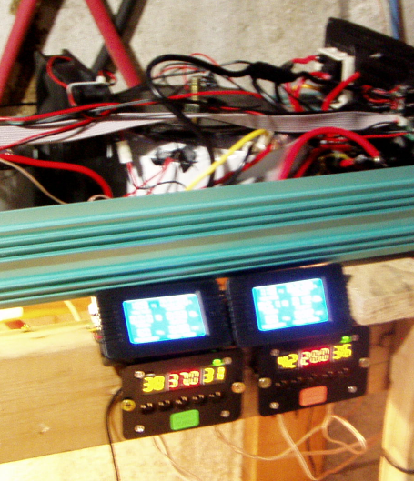
You need 12v to power them. I tuck one sensor into the fins of the same heatsink that powerjack mounts its sensor, and put the second sensor on the transformer near where powerjack puts their transformer sensor. One controller now displays transformer temp and the other displays mainboard heatsink (mosfet) temp. You can then set on and off temps for your fan based on actual temp readings from both sensors.
If your inverter has just one fan you just parallel the switch connections on both temp controllers and then connect that in parallel to powerjack's temp sensor on the transformer. That may not work on your inverter Kyle so you could alternatively connect to the two pins of the mosfet you shorted to make your fan run.
This setup not only allows very definite fan control, it also gives you a constant temp reading of your inverter.
If you need a 12v power supply, there are many to choose from. I use this one as in addition to powering the temp controllers, it can also power 2 or 3 12v fans easily (in case you want to add cooling to your inverter)
https://www.ebay.com/itm/152240514307?hash=item23723de503:g:0nUAAOSw6C5hCCkK
I have been using both of these exact items for years without a single one failing. Sadly the price of them has doubled since I last bought some, but still a fairly cheap and more reliable fix for your problems. Below is a pic of my temp controllers mounted in front of my inverter.
Hope this might be useful to you.
Now that I posted all that I see that your problems are solved. Oh well....
44 minutes ago, dochubert said:Hi Kyle,
I figured out some years ago that it was much easier (and more reliable) to just go around powerjack's flaky fan controls. Even when they work they turn on the fan at unpredictable times and frequently much higher inverter temps than I wanted. (The sooner your fan turns on, the less heating your inverter endures, and therefore the longer it will last - my theory anyway!)
To that end I don't interfere with powerjack's fan controls. Instead I add two of these:
https://www.ebay.com/itm/194245273137?hash=item2d39eba631:g:1lgAAOSwHONg8tW-
You need 12v to power them. I tuck one sensor into the fins of the same heatsink that powerjack mounts its sensor, and put the second sensor on the transformer near where powerjack puts their transformer sensor. One controller now displays transformer temp and the other displays mainboard heatsink (mosfet) temp. You can then set on and off temps for your fan based on actual temp readings from both sensors.
If your inverter has just one fan you just parallel the switch connections on both temp controllers and then connect that in parallel to powerjack's temp sensor on the transformer. That may not work on your inverter Kyle so you could alternatively connect to the two pins of the mosfet you shorted to make your fan run.
This setup not only allows very definite fan control, it also gives you a constant temp reading of your inverter.
If you need a 12v power supply, there are many to choose from. I use this one as in addition to powering the temp controllers, it can also power 2 or 3 12v fans easily (in case you want to add cooling to your inverter)
https://www.ebay.com/itm/152240514307?hash=item23723de503:g:0nUAAOSw6C5hCCkK
I have been using both of these exact items for years without a single one failing. Sadly the price of them has doubled since I last bought some, but still a fairly cheap and more reliable fix for your problems. Below is a pic of my temp controllers mounted in front of my inverter.
Hope this might be useful to you.
//content.invisioncic.com/g308908/monthly_2022_03/2144409729_tempcontrollers.png.8d0d6a1c8662cfb1a74bed61c8445691.png
So the new v11 boards DO use a larger TO-220 FET (my suggestion I guess!) and power the fans off battery voltage. A slight modification to the CPU firmware makes it so both thermistors will control the fan--meaning that they have gotten rid of the (frankly terrible) thermal switches. They've also removed the "fan override" switch.
One small step forward anyway.
So the new v11 boards DO use a larger TO-220 FET (my suggestion I guess!) and power the fans off battery voltage.
I think PJ hire you as their real design engineer as they use many of your design and I think more in the future to make the PJ inverter even better as my PJ never blow up FETs anymore any never overheat again .
as my PJ never blow up FETs anymore any never overheat again .
Yeah, but it can't run close to as much power output, either.