PLEASE NOTE: If you had an account with the previous forum, it has been ported to the new Genetry website!
You will need to reset the password to access the new forum. Click Log In → Forgot Password → enter your username or forum email address → click Email Reset Link.
If the GS 12kw has ATS grid backward then I do not have to go outside at night .
GS inverters all have automatic switch to grid based on the battery voltage setpoint you provide (and auto switch to battery by a different setpoint)...AND a local network webserver so you can literally push a button on your phone screen to manually switch the inverter to grid/battery from your easy chair if you want.
We're workin' on that 12kw...trying to get the chassis just right at the current time.
i am not connecting any of these inverters to the grid...they are all off grid....
i can connect 2 of the 24-volt batteries to get 48 volt but still will have to have an automated shut off to the 48 volt inverter to protect the lifepo4 ....
Ok, this is turning into too many chefs and not enough cooks and my policy on life is when you see something getting overly complex, try to not add to it so I think I will dip out of this conversation after this post.
SBMS0 has opto-coupled FETs, labelled as both opto and SSR in the circuit diagram, built in on the EXTIO3 line that is on the ExtConnector P3. I don't know the part number so I don't know exactly what is being used here but I can imagine what it is. Technically this gives isolation at this point but it is still possibly to kill these devices, as noted by Sid, if the specifications are exceeded, ie you can still damage the SBMS0 as a whole.
The 'arduino relay module' provides an extra layer between the SBMS0 and the outside world so unless you apply 1kV (or something equally stupid) to the relay module the SBMS0 will remain safe no matter what and given the apparent level of understanding of <a contenteditable="false" data-ipshover="" data-ipshover-target="/profile/29-pilgrimvalley/?do=hovercard" data-mentionid="29" href="/profile/29-pilgrimvalley/" rel="">@pilgrimvalley (no offence is intended, this is just how the skill set comes across to me) I think this would be an advantage.
There are guides available advising how to hook up an inverter to pin 5 and 6 on connector P3, if the inverter is suitable. The PJ is not IMO. The relay module is suitable. There are guides available to show how to wire things to connector P3 ping 5 and 6 using a pull up resistor so I won't detail all that here to avoid stuffing the thread full of more pictures and diagrams. Google finds them easily enough.
SBMS0 has opto-coupled FETs, labelled as both opto and SSR in the circuit diagram, built in on the EXTIO3 line that is on the ExtConnector P3. I don't know the part number so I don't know exactly what is being used here but I can imagine what it is. Technically this gives isolation at this point but it is still possibly to kill these devices, as noted by Sid, if the specifications are exceeded, ie you can still damage the SBMS0 as a whole.
If said SSR/opto-coupled FETs can handle 100v and 1A...the "inverter on" outputs on the 2 SBMS0 units (one per 24 bank) can easily be put in series, and directly control the PJ power switch line.
But this is dependent on 2 huge "IFs" which we still don't know:
- whether the SBMS "SSR" is rated for 80-100v (if they're opto-FETs, this is highly unlikely)
- whether the SBMS "SSR" can handle 1A current
- and that it's an optically-isolated device (presumed at this point, but not confirmed)
OK, so instead of working on GS stuff (like I probably should), I spent ~15 minutes digging for answers here on the SBMS0 thing, finding the following from Mr. Electrodacus himself:
QuoteEXT IOx (all of them) are the same and they are the output of an optoisolator Toshiba TLP172GM in case of the latest SBMS0 version and so the output is just a close or open circuit nothing else.
A quick websearch for TLP172GM turned up a datasheet (TLP172GM datasheet) which provides the following answers:
- maximum switching voltage is 350vDC (more than sufficient for an easy series-wired system)
- maximum switching current is 0.15A (way lower than I'd like to see)
- YES, it is opto-isolated (3,750v rated)
Another few more minutes with a very simple quick DMM check (which anyone with a PJ could do) turned up the following results (with a PJ Rev 9.00 control board setup on a 24v inverter--but as there is very little innovation in these inverters, this LIKELY will be similar to a Rev. 11.xx board. Check it yourself!)
<img alt="image.png.bece14978dba6c1459c743d0b562cf55.png" class="ipsImage ipsImage_thumbnailed" data-fileid="1239" data-ratio="133.33" style="height:auto;" width="384" data-src="//content.invisioncic.com/g308908/monthly_2022_04/image.png.bece14978dba6c1459c743d0b562cf55.png" src="/applications/core/interface/js/spacer.png" />
The highest I saw was ~15-20mA. Like I've said before on this thread, the power switch ONLY controls the power to the power supply IC (and a signal to the CPU)--it does not carry the power supply's load.
SO technically you could pretty well directly wire the "inverter control" lines from the SBMS0 to a PJ power switch.
Measure the current drawn by the PJ yourself before trying to control a PJ inverter via SBMS0; don't take my word for it! Do your homework first!
You must also consider the likelihood of the PJ failing (pretty likely if the law of averages is to be believed)--and the resultant possibility of the inverter overloading and burning out the TLP172 opto-FET switch in the SBMS0. (Damage would not go farther upstream from the TLP172 due to the opto-isolation.)
i believe Dacian the electrical engineer has this as open source (the SBMS0),,,, but my knowledge skill level is tiny working with these things transister, diode, resisters, mosfets. relays, optoisolators, inductors etc, but i am learning more so like i say '' hopefully don't make too many serious (dumb) mistakes"...
and reading and fully understanding wiring diagrams that is a whole other level of learning as they often have omitted connections that are required...
that is why "oberon" is developing the guide for the Electrodacus SBMS0 >>>> to fill in some of the missing blanks but he is an avid user on a boat i think...and not the electrical engineer developer....
the expensive lifepo4 battery is why , i am trying to get the automated ability to turn off the inverter and Powerjack are what i have to work with at the moment... i do have a go power 24volt 3000 watt with a remote on off as well. but this is primarily a PowerJack forum as i understand it...
bash them with the old sledge hammer, but I still need to have the automated shut down,,,, and PowerJack control at battery level SOC in not sufficient...almost any forum who talks about them does(powerjack inverters),, there are some who used to talk them up who now say not much more than a peep...🤔
it would be a big plus to have the SBMS0 as the control of discharge from the inverters (Powerjack or any other inverter for that matter)at the cell level monitoring state of charge that is does for some more user friendly compatible brands of inverters,,,
it does work with some brands of inverters,,,,like victron for sure and some others but i have the PowerJack to try to control...
yes, i have bought multi meters of various types but still learning...
thanks for your help....🤔🤔
i will post more when i can get more working..... busy with 4 bottle lambs, egg layers, and other animals in south dakota...
, and the continued work at the pilgrim valley farm in Bolivia South America also etc etc...
so thanks again for helping to get a possible workable solution to the biggest problem I see with PowerJack inverters at this time.... the inability to protect an expensive battery bank adequately....
later, 😎
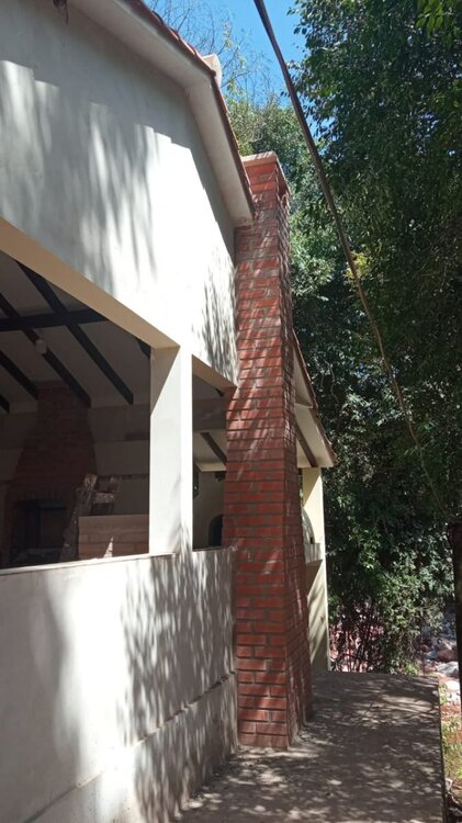
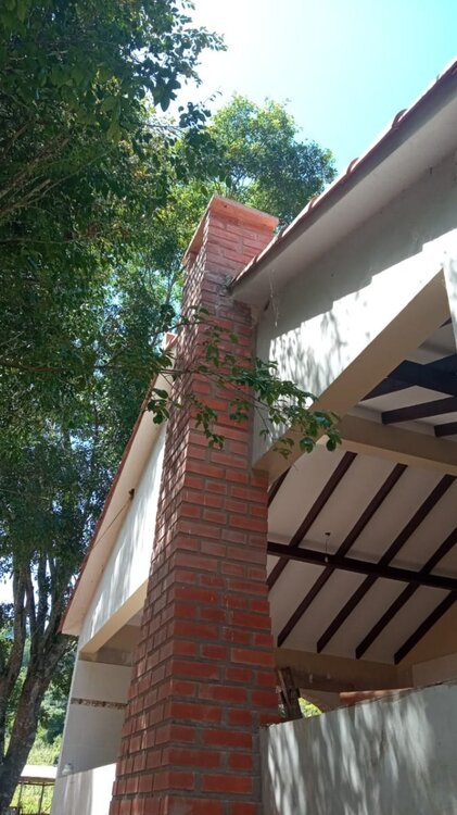
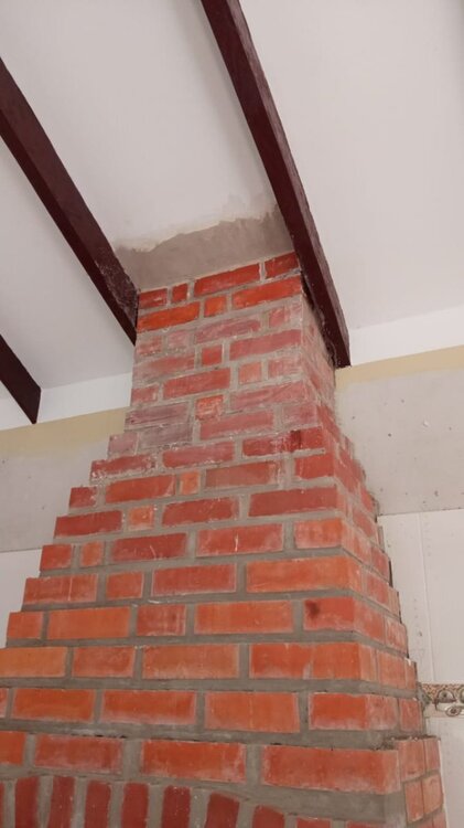
the pictures below are of my outside kitchen progress on April 1st 2022....it is all wood-fired >>>> pizza oven and 3 other cook areas so 3 brick chimneys.... in Siacan which is in the southern part of Bolivia about 75 miles as the crow flies to Argentina....it is subtropical there and covered with hardwood forest for the most part... Pilgrim Valley is the name of my mountain getaway... a 21 year project continues...
PowerJack claims to be celebrating 18 years of inverter manufacture somewhere i read!!!
i started with atari and commodore and ibm pc clones some 40 plus years ago....the survivors made changes to their products to keep up with new electrical innovations.... currently a dell computer fan....
not a typist either.... i hired the term papers typed for me in college!!!
The highest I saw was ~15-20mA. Like I've said before on this thread, the power switch ONLY controls the power to the power supply IC (and a signal to the CPU)--it does not carry the power supply's load.
this was one of the details i needed to the solution,,,, that is why i previously asked the question...
Right now I watch the LED light flickering and go outside at night to recharge the low battery . If the GS 12kw has ATS grid backward then I do not have to go outside at night .
right !!! that is a pain in the rear not to have the ability to automatically shut down the inverter when the discharge level is too deep to adequately protect the battery... the shut down at the gross battery SOC is inadequate to protect any type of battery.... if one cell goes haywire due to a bad connection or what have you....
more a pain in the rear when you have to go outside in the howling winds at 40 below zero wind chill which can occur in rural South Dakota... i had a door lock freeze one year and had to break out a window to get into the house...then cover with cardboard until spring when glazing was more readily done...🤣
i will not be having any grid tie to this solar pv off grid system from the inverters,,, have not for over 2 years and will not in the future either.....
thanks for your help,,,,😎
the assumption that one reads everything in a forum is definitely the assume word...
i was taught no question is a dumb question....
how else would one learn?
gotta go feed the critters again...
my present specialty is building and remodeling, and care of livestock....
I am a chemistry major among other things... but not an electrical engineer,,, my college room-mate was....42 years ago.
😎
more a pain in the rear when you have to go outside in the howling winds at 40 below zero wind chill which can occur in rural South Dakota.
The highest I saw was ~15-20mA. SO technically you could pretty well directly wire the "inverter control" lines from the SBMS0 to a PJ power switch.
this was one of the details i needed to the solution,,
That is the information I need to make SBMS0 to auto shut off the Powerjack but have to wait till SBMS0 is back in stock .
the assumption that one reads everything in a forum is definitely the assume word...
i was taught no question is a dumb question....
how else would one learn?
gotta go feed the critters again...
my present specialty is building and remodeling, and care of livestock....
I am a chemistry major among other things... but not an electrical engineer,,, my college room-mate was....42 years ago.
😎
I put the PowerJack 16000 watt LF PSW SP AMG version on top of the PowerJack 20000 watt LF PSW SP AMG version and they are in the exact same physical dimensioned stainless steel case.
going to have to pop the top off both to see what the differences are....
hope they did not pull the switch-a-roo by simply putting a different sticker on the top of the case????? 🤔🤔🤔🤔
these are sold as powerjack with powerjack warranty of 15 months and you register for the warranty through powerjack....😒😒
I put the PowerJack 16000 watt LF PSW SP AMG version on top of the PowerJack 20000 watt LF PSW SP AMG version and they are in the exact same physical dimensioned stainless steel case.
the 16000 watt one has 32 amp breakers and the 20000 watt one has 40 amp breakers.
had to snag the magnifing glass, my glasses, and a flashlight to read that... darn i really need real glasses not the dollar store cheaters...
they are both pre-jumpered on the outside terminals to do 120 volt output... so may or may not change that when i hook them into the AC breaker panels...
again all of this is strictly off-grid.... there is no connection to the grid in any way and there will not be in the future either....
I think the Electrodacus SBMS0 will be in stock in June 2022 is his latest prediction (Dacian at Electrodacus)along with the Electrodacus DSSR20's due to the semiconductor shortage... he has a pic and place machine to assemble things....parts availability is the Electrodacus hold up.... as with other small manufactures/ assemblers also have thge similar reported supply line difficulties...
the SBMS0 is the only model made now...
all the other bms models from Electrodacus were discontinued for the new more modular SBMS0......
i bought some mg 847 carbon conductive paste for the LiFePO4 cell assembly from Digikey and it arrived in 2 days....it says it has a 60 month shelf life???🤔
Amazon order arriving today 4/4/2022... 4 days due to the weekend slowing it some...
so some places are super fast shipping; vs the slow boat from china route....
sun is out and it is a great day...
thanks all 😎
5.3 Switched trigger circuits: above 50mA If your devices are on/off triggered, and the total switching current needed on one EXTIO port is above 50mA, then you will need a relay — ideally, an optically-isolated solid-state relay (SSR). Here are some examples to choose from: • The SSR-25DD and DC60S5 are panel-mounted options. They’re overkill for most applications, but easy to use. • The CPC1706 is a good choice for many circuits, and has a maximum load current of 4A, but it needs to be soldered into perfboard or other circuit board. If you need to reverse the on/off signal, which is common for EXTIO Type 3, 4, & 5, you can use the CPC1705 or other normally-closed SSR. • The 817 optocoupler board, available on Amazon, is popular, but not particularly high-quality. Remove the red jumpers if you use it. In order to power the relay, you’ll need to connect the EXTIO+ through a resistor to your positive distribution busbar, and the EXTIO− to the SSR input positive. Then connect the SSR input negative to your negative busbar. Your device(s) can now be switched by the SSR load terminals. You can also add more than one SSR in parallel on a single EXTIO as long as the total draw is under 50mA. The size of the resistor depends on the minimum switching current that’s required by the SSR. For example, a CPC1706 requires 5mA to activate, so for a 24V battery, the resistor can be a maximum of 24V ÷ 0.005A = 4,800 . Ω To give a safety margin, you may want to size it around 3,000 . Then to check the power rating for the resistor, V Ω 2 /R = 242 ÷ 3000 0.2W, so with a ≈ healthy safety margin, a 0.5W resistor will work well.
The Powerjack on/off switch can be control by the above . The 'arduino relay modules' are pre-built and ready to go, pretty cheap, and available from just about every place imaginable, certainly Amazon. Arduino relay modules can also be use or Sid transistor circuit with relay can also be use . I will make one when the SBMS0 is available .
<a href="/monthly_2022_04/2106913666_Screenshot(1022064).png.8ac897e962bbb264cb23296752e184be.png" class="ipsAttachLink ipsAttachLink_image"><img data-fileid="1274" src="//forums.genetrysolar.com/applications/core/interface/js/spacer.png" data-src="/monthly_2022_04/1318444160_Screenshot(1022064).thumb.png.577ecf649453e4a7c33ffc58c772b03c.png" data-ratio="56.1" width="1000" class="ipsImage ipsImage_thumbnailed" alt="Screenshot (1022064).png">
