PLEASE NOTE: If you had an account with the previous forum, it has been ported to the new Genetry website!
You will need to reset the password to access the new forum. Click Log In → Forgot Password → enter your username or forum email address → click Email Reset Link.
Not to mention that the H-bridge charge function is incredibly inefficient. You can tell that just by the amount of heat the thing will blow out when in charge mode. I'd be suprised if the efficiency is over 60%.
I use a Powerswitch PSW2460 (full range specs at https://www.moriraddrizzatori.it/en/products/battery-charger/high-frequency/power-switch.html ) when I want to charge my 24v bank of SLA GEL batteries from grid power. Quoted efficiency is > 85%.
Not to mention that the H-bridge charge function is incredibly inefficient. You can tell that just by the amount of heat the thing will blow out when in charge mode. I'd be suprised if the efficiency is over 60%.
I would be surprised if a PJ inverter's charge efficiency is over 50%.
Because I've measured GS inverter charge at 58-60%...utilizing a stock PJ mainboard, though. With either a GS-design mainboard or GS "LegacyFET" boards, the charge efficiency increases to ~72-75%. I'm hoping to figure out how to get it to at least 80% at some point...
For now I'll be using an outboard charger -- made that decision in the last week or so.
The GS FET boards are in and I'm installing now.
1. I've got thermal paste but none that's specifically electrically conductive. I suspect it's relatively dialectic in nature (the white stuff) but it's certainly not going to prohibit metal to metal contact in spots, not to mention that screw contact on the opposite side. I feel like that's plenty of electrical conductivity for use with a dialectric thermal grease -- but please correct me if I'm wrong!
2. More importantly, these GS FET boards have only 4 FET's per board with the outer two positions on the boards unpopulated. That's 4 FET's on the GS boards vs 6 on the failed PJ FET boards. I understand that you're using different FET's which perform differently (and theoretically better) than the originals; please confirm that these 4-FET boards are a satisfactory replacement for the 6-FET boards used in the latest 8k units.
Thanks!
32 minutes ago, Mike T said:1. I've got thermal paste but none that's specifically electrically conductive. I suspect it's relatively dialectic in nature (the white stuff) but it's certainly not going to prohibit metal to metal contact in spots, not to mention that screw contact on the opposite side. I feel like that's plenty of electrical conductivity for use with a dialectric thermal grease -- but please correct me if I'm wrong!
Wouldn't make a difference, I don't think.
Thing is, the FETs generate so little heat in a proper GS design, that heatsink paste is kinda an unnecessary cost/complexity.
33 minutes ago, Mike T said:2. More importantly, these GS FET boards have only 4 FET's per board with the outer two positions on the boards unpopulated. That's 4 FET's on the GS boards vs 6 on the failed PJ FET boards. I understand that you're using different FET's which perform differently (and theoretically better) than the originals; please confirm that these 4-FET boards are a satisfactory replacement for the 6-FET boards used in the latest 8k units.
Umm...?????!?
I'm not aware of a single GS FET board yet released/sent to the field that should have just 4 FETs/board. Can you provide a photo of the boards you have? ...PJ's the only one that ever has done 4 FETs/board.
I didn't wait for reply to above -- temporarily installed the FET boards without thermal grease and installed the new driver board. I inspected everything else and couldn't visually spot any problems. I connected the inverter unit to a car battery with a set of 6 ga jumper cables, as these were easily accessible to my work bench. One LED on the main board illuminates and one led on the driver board illuminates. This seems to be different than Dickson indicated in his post above. It is, by the way, the version 11.3 board.
With a large shop vac as test load, the unit went into low-voltage protect mode, probably due to small power cables and battery. With a small box fan as a test load, however, the inverter works just fine.
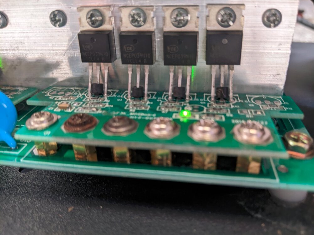
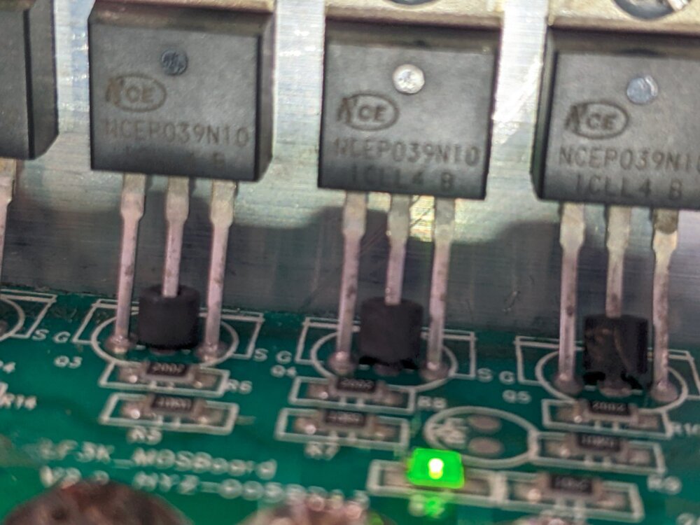
Now that I see your reply, I'm a bit alarmed. Photos are attached -- please advise!
1 hour ago, Sid Genetry Solar said:Umm...?????!?
I'm not aware of a single GS FET board yet released/sent to the field that should have just 4 FETs/board. Can you provide a photo of the boards you have? ...PJ's the only one that ever has done 4 FETs/board.
Photos show 4 FET's -- I didn't notice this when ordering...
https://www.genetrysolar.com/parts/mosfet-board-for-48-volt-10k15k-power-jack-inverter-684zr-7d748
Photos show 4 FET's -- I didn't notice this when ordering... https://www.genetrysolar.com/parts/mosfet-board-for-48-volt-10k15k-power-jack-inverter-684zr-7d748
Yeah, those are Power Jack spare parts from the GS website.
Proper (new) GS FET boards look considerably different.
If you're working with a PJ inverter...heatsink compound won't hurt. Things run so hot anyway. I gooped up the FETs in my "9kw PJ" with thermal compound before putting it into service (tranny overheats at 3kw of course).
One LED on the main board illuminates and one led on the driver board illuminates. This seems to be different than Dickson indicated in his post above. It is, by the way, the version 11.3 board.
Your mainboard has the 4 mosboard from Sean and look like the 4 mosboard LED is on green and all FETs are good . Some LF driver like your the LED is on green and is working good . MY
My new LF driver LED is OFF and is ok , IF the LED is blinking then the control board is bad . Your control board may have 2 LED on STEADY and should not be Blinking . Look like your inverter is working good . Your inverter will work with 4 FETs per mosboard just as well as 6 FETs per mosboard . I do not use paste on the FETs . A 12v dc Delta fan will keep the FETs cool .
input 110VAC and battery power, to be sure the unit worked out of the box. It did, as far as I was able to ascertain, but failed instantly when hooking it up in a permanent installation. A permanent installation require a transfer switch if connect to the grid . The main service should be OFF to not backfeed the inverter output . I do not know what your permanent installation is . The inverter works good using extension cord .
On 12/9/2022 at 6:22 PM, Mike T said:So, with that understood, I suspect the cause of the spectacular failure, was that the neutral connected to the LFPSW's input N terminal has already been bonded to ground somewhere up stream (generator? ATS???). When the outputs of the LFPSW unit route through the second transfer switch to the breaker box, ground is bonded back to neutral and you end up with a situation where input neutral, output neutral and ground, as connected to the LFPSW unit, are all at the same electrical potential. I don't know this for a fact, but I suspect this unit isn't designed to have the input and output neutrals at the same potential...
Am I correct -- is this my problem?
I am convinced that you and me had the same issue, tripping breaker and blowing off FETTs . My 12000w LF AGM a complete disappointment, no instructions manual . After testing and testing I finally realized PJ unit will Tripp and burn fetts once connected to any type of ground ;independent or household .My biggest mistake I was connecting ground the to the chassis E .independent earth ground or the house ground connection is bad for the unit , AC receptacle output as well ( Has To be connected to L and N only otherwise bonded and feed back (114v between E and N.)
is this normal operation with PJ?
9 hours ago, Lener said:is this normal operation with PJ?
Should not be.
Like I've stressed earlier in your thread (<a contenteditable="false" data-ipshover="" data-ipshover-target="/profile/208-lener/?do=hovercard" data-mentionid="208" href="/profile/208-lener/" rel="">@Lener), there should be no continuity from any of the input AC, output AC, or battery terminals, to the chassis.
If there's a short between any of those terminals and chassis, that would be the problem (likely deadshorting the output of the inverter due to ground-neutral bonding at the external breaker panel).
On 12/30/2022 at 8:35 AM, Sid Genetry Solar said:Should not be.
Like I've stressed earlier in your thread (<a contenteditable="false" data-ipshover="" data-ipshover-target="/profile/208-lener/?do=hovercard" data-mentionid="208" href="/profile/208-lener/" rel="">@Lener), there should be no continuity from any of the input AC, output AC, or battery terminals, to the chassis.
If there's a short between any of those terminals and chassis, that would be the problem (likely deadshorting the output of the inverter due to ground-neutral bonding at the external breaker panel).
Sid -- I just checked and the "E" input terminal is at the same potential as the chassis ground stud -- so that's something at least. Should not cause a problem -- just thought I'd mention it.
I mounted the unit in my RV for a proper test run. I removed main power from the main breaker and connected the output of the inverter to the the main breaker. The following loads were active:
-11A for water heater (purely resistive -- tough load)
-Maybe 4A surge to start the refrigerator after which .5A to keep it going
-11A resistive or so for the battery charger
-Negligible load for one single 60w equivalent LED bulb
When I turned on the inverter, it made a pretty notable sound but seemed stable. I ran indoors to observe the LED light (the inverter was mounted in the "belly box" storage area behind the 5th wheel). The LED light was quite dim. I ran back outside to get a meter and was about to measure output voltage when I heard an FET fail. I turned off the unit as fast as I could.
I mentally went through the list of items that would load the inverter before I turned it on, and totally forgot the battery charger. I would have preferred to have run the test without the battery charger -- BUT -- I would have expected the inverter to simply go into protect mode if the load was too much.
This may be a deal breaker if the inverter isn't intelligent enough to shut itself down under an excessive load. Thoughts? Experiences?

