PLEASE NOTE: If you had an account with the previous forum, it has been ported to the new Genetry website!
You will need to reset the password to access the new forum. Click Log In → Forgot Password → enter your username or forum email address → click Email Reset Link.
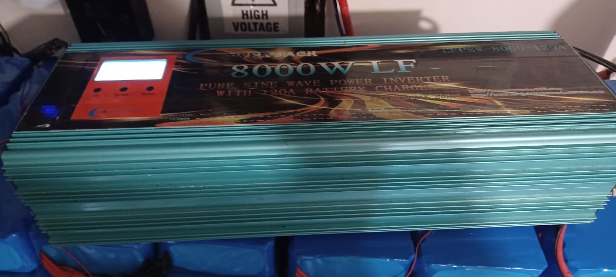
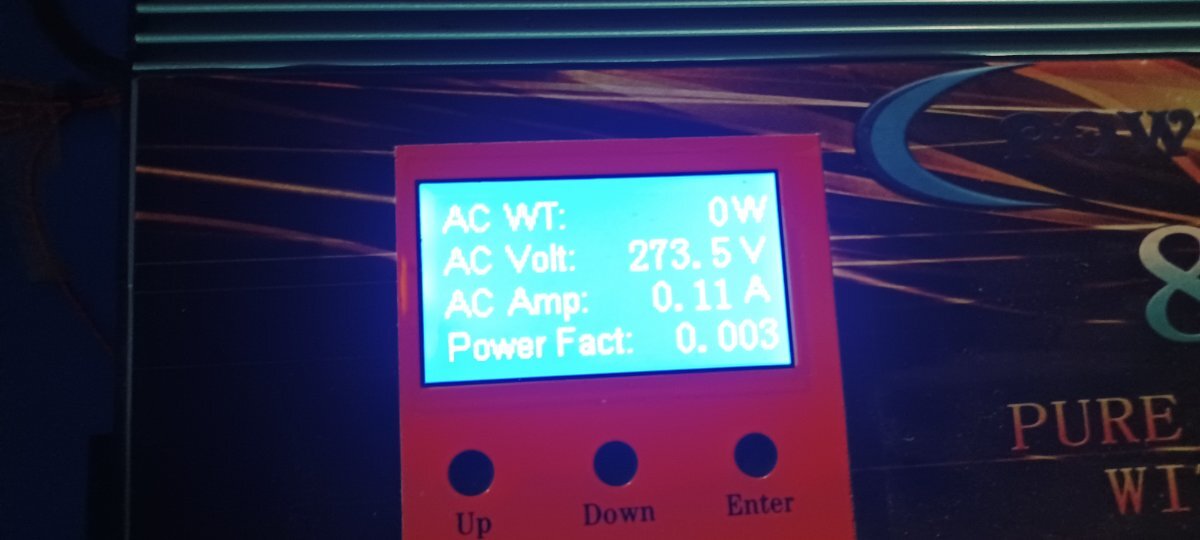
Hello, I bought this inverter, it is more backward than the previous one, on the boards it reads 2016 and the transformer 2017, it is giving 275v A/C output, here only 240 is used, I would like to know how to lower that voltage since this inverter does not It has a low voltage knob, it only has a battery knob. thanks for your help.


Your options are kinda limited...
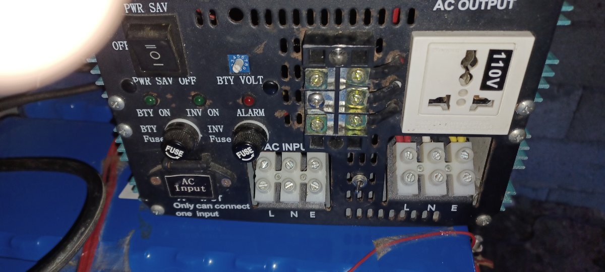
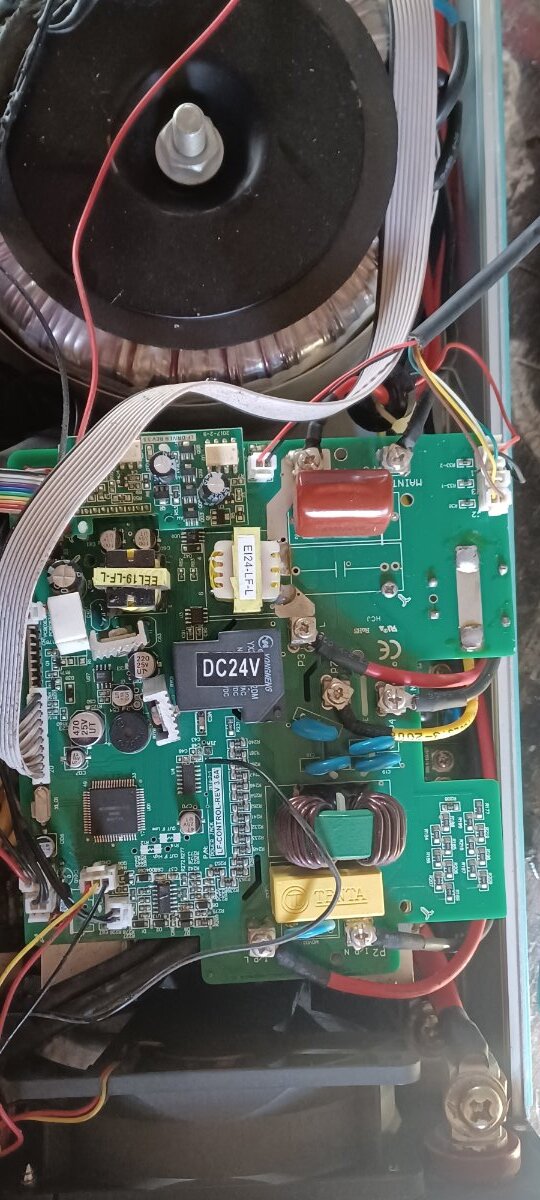
Can you provide a photo of the control board?
Also verify the output voltage with a multimeter. (Can't trust the LCD!)
Sorry, the photo of the 5k was not there, the inverter is 8k, I can provide you with more photos later, since I am working at this time, (police department) and yes, I tried it with a fluke brand tester, and it offered that voltage (275) should be noted the inverter is split phase.
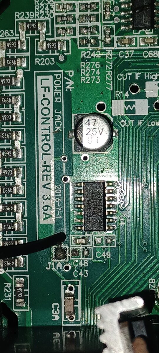
Seeing as there's no easy options for adjusting the voltage (especially on these older boards--which I'm not very familiar with), the easiest way to reduce the output voltage would be to bypass part of the resistor ladder that provides the AC voltage feedback to the MCU.
<img class="ipsImage ipsImage_thumbnailed" data-fileid="1815" data-ratio="188.09" width="277" alt="image.png.625b33eda4f86bc9043479af16a8fd5a.png" data-src="/monthly_2022_11/image.png.625b33eda4f86bc9043479af16a8fd5a.png" src="/applications/core/interface/js/spacer.png" />
Try bypassing just one block (which takes 2 resistors out of the circuit), and see how it behaves. By increasing the sensed feedback voltage, the MCU should lower the output voltage in response. If bypassing one block isn't enough, try bypassing 2 blocks.
Worth noting that these are 499K resistors, so there is pretty much zero current flow here.
Perfect, I'll check tomorrow, I'll let you know anything. Thank you
15 hours ago, Sid Genetry Solar said:Seeing as there's no easy options for adjusting the voltage (especially on these older boards--which I'm not very familiar with), the easiest way to reduce the output voltage would be to bypass part of the resistor ladder that provides the AC voltage feedback to the MCU.
<a href="/monthly_2022_11/image.png.625b33eda4f86bc9043479af16a8fd5a.png" title="Enlarge image" data-fileid="1815" data-fileext="png" rel="">
//content.invisioncic.com/g308908/monthly_2022_11/image.png.625b33eda4f86bc9043479af16a8fd5a.png
Try bypassing just one block (which takes 2 resistors out of the circuit), and see how it behaves. By increasing the sensed feedback voltage, the MCU should lower the output voltage in response. If bypassing one block isn't enough, try bypassing 2 blocks.
Worth noting that these are 499K resistors, so there is pretty much zero current flow here.
19 hours ago, Sid Genetry Solar said:Seeing as there's no easy options for adjusting the voltage (especially on these older boards--which I'm not very familiar with), the easiest way to reduce the output voltage would be to bypass part of the resistor ladder that provides the AC voltage feedback to the MCU.
Is this what the pot on the variants with a voltage control is doing? More voltage drop, lower read voltage, harder it works to hit voltage.
Solder in a few mega-ohm pot and get a simple variable voltage control. Nice, simple, workaround.
Out of curiosity, what do you think could cause a 60v increase in output? Seems to me like only the regulator interpreting the wrong voltage and overdriving to compensate...

A v3.6 control board! I'm jealous! My best powerjack (still running my house) has a v3.4 control, which in my limited experience is the best control board powerjack ever made. Your v3.6 looks just like it and can't be too different. Hopefully you can get the voltage down to normal. Solderiing across the points Sid circled should bring it down some, probably between 10 and 20v. As he said, you might have to short out another pair, or even two more(just do one at a time, though).
The only other thing I can suggest is doing a thorough cleaning of the control board(top and bottom) as a bit of dirt in the wrong spot can make these things do weird stuff.
21 minutes ago, NotMario said:Is this what the pot on the variants with a voltage control is doing? More voltage drop, lower read voltage, harder it works to hit voltage.
You hit the nail on the head.
...the side effect being that now the CPU has no idea what the actual output voltage is.
Somewhat comically, PJ literally hand-replaces 2 SMD resistors on the control boards to switch between 110v and 220v regulation. CPU code stays the same--and has no idea of the actual output voltage.
21 minutes ago, NotMario said:Out of curiosity, what do you think could cause a 60v increase in output? Seems to me like only the regulator interpreting the wrong voltage and overdriving to compensate...
Could be anything, all the way down to dust/"dusty goo" buildup on the PCB. The "isolation" path from the AC output to the feedback amplifier is literally >16MOhm of resistors, so mashing your fingers on those resistors will change the output voltage significantly.
20 minutes ago, dochubert said:A v3.6 control board! I'm jealous! My best powerjack (still running my house) has a v3.4 control, which in my limited experience is the best control board powerjack ever made. Your v3.6 looks just like it and can't be too different.
hehe, "best one they ever made"--and that's because it's a direct shameless copy of the "original design" inverter that all Chinese LF inverters are based off of! Before any cheapening mods were made without understanding how the circuit actually worked....
7 minutes ago, Sid Genetry Solar said:Somewhat comically, PJ literally hand-replaces 2 SMD resistors on the control boards to switch between 110v and 220v regulation. CPU code stays the same--and has no idea of the actual output voltage.
Hey, Little bit off topic...
My U-Power seems to be 110v regulated. (L2 does not reach control board).
What is the practical difference? Second leg can have too much voltage sag?
Second leg can have too much voltage sag?
A bit. Sag will be determined by transformer losses--as obviously, if L2 is pulling power from the core, it will cause a sag in L1 (just less the L2 winding resistance). And the inverter will try to regulate L1.
You get no current limit on L2 though. As though that makes much of a difference though 😉.
A v3.6 control board! I'm jealous! My best powerjack (still running my house) has a v3.4 control, which in my limited experience is the best control board powerjack ever made. Your v3.6 looks just like it and can't be too different. Hopefully you can get the voltage down to normal. Solderiing across the points Sid circled should bring it down some, probably between 10 and 20v. As he said, you might have to short out another pair, or even two more(just do one at a time, though).
Actually yes, the boards are a bit dirty, I'll try that first to see what happens. Thank you
On 11/7/2022 at 10:35 AM, Sid Genetry Solar said:that's because it's a direct shameless copy of the "original design" inverter
I've heard that original LF inverter was designed by Trace (before they were bought by Xantrex). Any idea if that's true? If so, I wonder what the brand name/model of the first LF inverter was? And are any of them still around? I know there are a few old Xantrex/Trace inverters still around, but are they that first "original" design, or were they copying something still older?
One more 'wonder'. I wonder who claims to be the original designer of that original LF inverter? They can't be blaming that on Tesla!
I've heard that original LF inverter was designed by Trace (before they were bought by Xantrex). Any idea if that's true? If so, I wonder what the brand name/model of the first LF inverter was? And are any of them still around? I know there are a few old Xantrex/Trace inverters still around, but are they that first "original" design, or were they copying something still older?
I don't know either. Jack might admit to it if I ask, but I don't see that as being important at the moment.
One thing is for sure, the design was well-done for what the designers had available at the time. That little barebones 68HC11-based processor on the "original" control boards is literally completely maxed out generating an SPWM output--and a lot of support circuitry on the output was due to the internal peripherals not having it!