PLEASE NOTE: If you had an account with the previous forum, it has been ported to the new Genetry website!
You will need to reset the password to access the new forum. Click Log In → Forgot Password → enter your username or forum email address → click Email Reset Link.
As an update, I took the long road to get back to where Sid sent me at the beginning... I needed an isolated gate supply... So I used an old audio amplifier, as you can see in the first pic. It has a TL494 PWM IC driving a cute little toroidal transformer at 37 kHz. There is no voltage feedback. The transformer had two secondaries joined together in the middle to form a dual rail +-25 volt balanced output. Since there was no feedback to bother with, I was able to separate the two windings from the board and electrically isolate the two outputs. I also chopped off the amplifier section off the board, pic 2. But that output is still AC at 37 kHz, so I made rectifier and filter on a separate board, pic 3 and 4.
Since there are two isolated AC outputs, I decided that I would rectify and filter them separately and keep them isolated. This plays into a future project nicely. Then I used some regular eBay buck converters on each output to regulate the voltage, also pic 4.
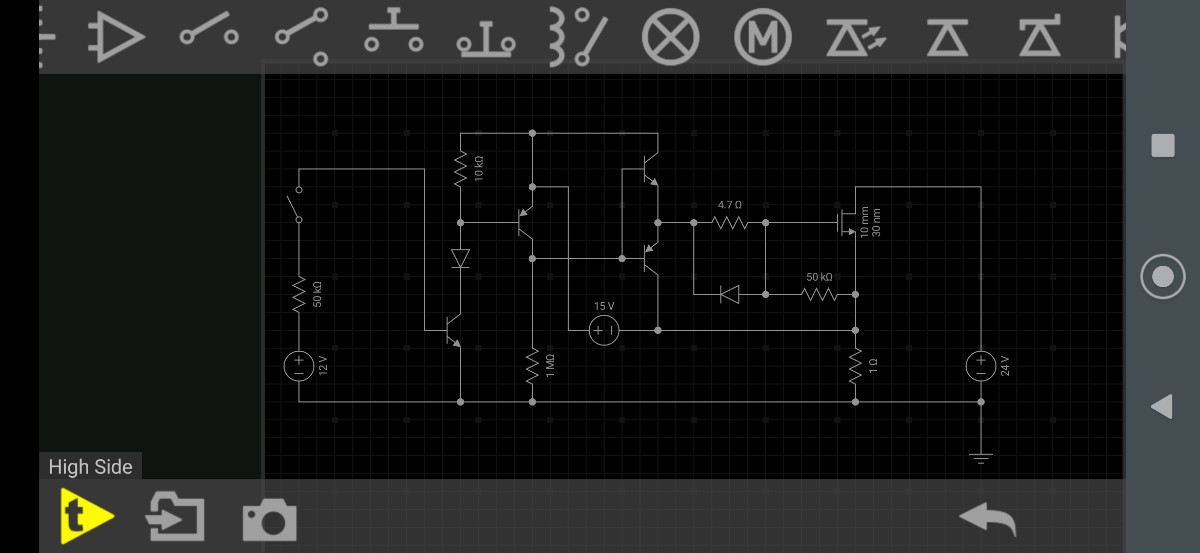
I tried the transistor interface from pic 5 as a control scheme. It sorta kinda works, but not as I expected. There's a fundamental gap in my understanding of transistor physics, apparently.
So I used a PC817 optocoupler and an inverting Schmitt trigger. The trigger was powered by the isolated power supply. And it worked ok as an On/Off control. But once the PWM started, it quickly under-performer. Especially over 2 kHz. It would work fine as a speed controller for a motor or an LED dimmer, but for the project I'm building this to culminate in, it would fail totally.
I said all that to say this: I disassembled a bad VFD motor drive to harvest the capacitors. But I found some of the TLP350 opto gate drivers inside! So I breaded boarded a circuit to test... And it is as good as it gets! Pic 5 and 6 show a test signal in yellow and the output in green. These are at low frequency, but I took it all the way to 40 kHz before it started to show any distortion. But I think most of that is from sloppy breadboard wiring. Now I'll clean it up. Yes I know this is a crazy way to do stuff, but one goal of a lot of my projects is to see if I can do stuff with what I have on hand with as little special orders as possible. Thanks Sid


Ha, I guess they make gate drivers for a reason then 😉
Glad to be of assistance.