PLEASE NOTE: If you had an account with the previous forum, it has been ported to the new Genetry website!
You will need to reset the password to access the new forum. Click Log In → Forgot Password → enter your username or forum email address → click Email Reset Link.
I have a 2020 model 15KW 48V inverter. After using it for a few months, I'm curious if the peculiar behavior I've noted is exclusive to my unit or if there are others with the same problem(s). I have it connected to the breaker panel feeding the whole house.
Somewhere around 350W L1 output/load, the output causes the light bulbs in my house to flicker @ 60hz with varying intensity. If you look away from the bulbs, the rooms seems as if it were lit by flickering candlelight. It doesn't seem to matter what the load is, I get the same results with many different loads regardless of whether they are resistive or reactive.
Also, the idle current fluctuates from approx 35-80 watts at a rate of about 1hz. With the fans off, you can hear the buzz/hum in the transformer changing with the same rate, mimicking the fluctuation of the idle current.
Has anyone else noticed similar behavior? Have you been able to correct it?
Have I had this problem? Absolutely.
This problem is entirely caused by the voltage regulation code in the CPU, which has no hysteresis. It is either turning up the throttle, or turning down the throttle--which obviously will cause an oscillation. Funny part is, the oscillation is on a 60Hz basis (+1 / -1 on the high wave, low wave), causing one of the two L_MOS to run hotter than the other.
Adjusting the voltage regulation knob seems to "adjust" this issue--but as it's caused by the firmware, there isn't much of anything that can be done from a hardware perspective to fix it. And of course, the loading on the inverter "adjusts" it further. The best I could do with hardware (small signal capacitors, etc.) was get it from a 15 or 30Hz big oscillation all the time, to a 60Hz small oscillation most of the time.
Genetry Solar does have (in-house) revised PJ firmware that corrects this problem. (And both L_MOS stay about the same temperature.) If you have a v4-v9 PJ control board (with the removable CPU), you could buy a WiFi board upgrade kit from Sean (which comes with a replacement reprogrammed CPU board)--this will allow you to tweak, tinker and adjust a plethora of settings in the inverter. As well as fix the flickering issue. And give PWM fan control based on temperature. (FWIW: the WiFi board allows OTA updates, so I can provide an update to tweak/add features as necessary.)
Thanks for the reply!
I would love to install a WiFi board but i have v10.03 control board. Is there a solution that will work in my unit? I'm willing to experiment and guinea-pig if need be. I do have 20years electronics background (mainly RF and mobile 12vdc electronics) and a full bench w/ scope, sig gen, freq counter, spectrum analyzer, power supply, etc. Before i found genetry I had planned to reverse engineer this inverter but I hate to re-invent the wheel as it looks like you guys have 'er pretty well figured out.
I would love to install a WiFi board but i have v10.03 control board.
Sigh. Unfortunately not an easy one. To go the Genetry route with a 10.3 (unified) control board would require Sean shipping a replacement pre-programmed 10.3 control board out with a core charge (refundable upon return of the 10.3 board you have). Also your inverter chassis probably doesn't have a spot to mount the WiFi LCD board...count yourself really lucky if you got one of the units that has a plate covering up the LCD cutouts. That was our suggestion; I have no idea how many were produced that way (though I have personally seen 1).
Once I finally get these Genetry inverters fully finished, I plan to go back to PJ and update their design (save them some money in the process!) The updated CPU code I'll provide them would support the WiFi board, so it would be a fairly simple addon at that point.
Also hoping to provide an upgraded drop-in LF Driver that will actually drive those FETs pretty cleanly, and solve a lot of the FET heat (even though the transformer is the weakest link). Only so much I can do from day to day though 😉
I really enjoy how many customers digging into these units have significant electronics background and test equipment...that's always a bonus.
I guess I should summarize: yes, it's possible to run the GS upgrade on a 10.3 PJ inverter--just up to you how much work you're willing to go through to make the upgrade.
2 hours ago, Sid Genetry Solar said:I guess I should summarize: yes, it's possible to run the GS upgrade on a 10.3 PJ inverter--just up to you how much work you're willing to go through to make the upgrade.
Couldn't you use one of the V 8 board kits and then go with the WiFi board. It would still require cutting the hole for the LCD unless he has the plate on the side.
Couldn't you use one of the V 8 board kits and then go with the WiFi board.
Could be done--though if he doesn't have a v8.0 board laying around, then he might as well go with a v10.3 replacement board and the core charge.
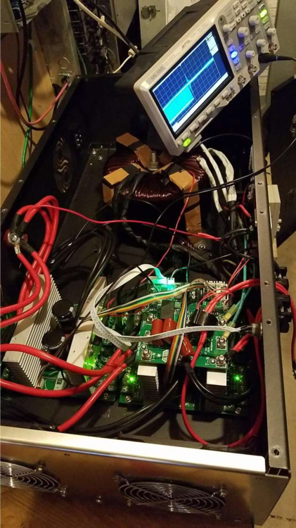
Thanks, I will check with Sean about the 10.3 upgraded board. I do have the cut-outs to install the lcd but I am not opposed to mounting it elsewhere as I have already removed the plate in order to pass the wires for my transformer through the holes. I suppose that I should mention, knowing the transformers are the weakest link here, I have removed mine and installed it in a bath of 4 gallons of mineral oil for cooling. pics available if anyone is interested...
So far this has worked extremely well for me. So well, in fact, the fans have yet to turn on via thermal switch. I have noticed the resistors on the mosboards run pretty hot (about 50* over ambient temp) though without some air movement, so I have the 2 of the fans on that end running at reduced speed to keep everything cool. the other fans are connected to energize w/ the thermal switch.
I've seen it mentioned before that disconnecting one of the 2 mainboards can be beneficial. Is there a significant reduction in losses or increase in stability (is it worth the effort)? my MOS boards only have 4 Fets installed; if I were to disconnect a mainboard would you suggest adding the additional Fets and resistors?
Thanks, I will check with Sean about the 10.3 upgraded board. I do have the cut-outs to install the lcd but I am not opposed to mounting it elsewhere as I have already removed the plate in order to pass the wires for my transformer through the holes.
So the WiFi board would only use one of those cutouts. It is worth noting that the "output board" would need to have the parts (a transformer, connectors, and a few resistors) installed for voltage/current feedback to work. It's hit or miss whether PJ included them on the board.
The WiFi board is intended to be mounted to the chassis, as there's over 50 wires that can connect to a fully loaded WiFi board. Battery power...up to 6 fans (PWM) or 3 fans (2-wire)...up to 6 thermistors...plus the feedback and CPU communication cables.
I have noticed the resistors on the mosboards run pretty hot (about 50* over ambient temp) though without some air movement
I would presume that this is the snubber resistor (R3 on the short MOS boards, or R14 on the long MOS boards), not all the gate resistors? (LF Driver is far too weak to get the gate resistors hot, haha!)
I've seen it mentioned before that disconnecting one of the 2 mainboards can be beneficial. Is there a significant reduction in losses or increase in stability (is it worth the effort)? my MOS boards only have 4 Fets installed; if I were to disconnect a mainboard would you suggest adding the additional Fets and resistors?
Disconnecting the 2nd mainboard is most beneficial on inverters using the older long mainboards (over 12" long) with 6x HY3810 FETs per MOS board. The PJ LF Driver is far too weak to drive a single set of 6 FETs (easy to see with your 'scope--those gate drive signals are very rounded)...which is why adding a 2nd mainboard of those heavy FETs often tended to cause the inverter to run hot at no load. "Memo, PJ: the sine wave should be on the output of the inverter, not on the FET gates" 🤣
With your setup having (most likely) 2 short mainboards (~6" long) and only 4 of the newer NCEP039N10 FETs per board, you're probably alright with the double mainboard setup.
the other fans are connected to energize w/ the thermal switch.
Gotta love that thermal switch. Nothing like putting a 0.5A 30vDC rated switch on 3 amps of 55v fans...what could possibly go wrong??
Upload pictures of the unit and we can tell you what will be needed for an upgrade. Obviously a full control board wifi board upgrade would work out of the box and would eliminate alot of the hardware found inside the inverter. The downside is you need to make 2 pin connectors for the fans to plug in as well as a the positive and negative supplies to the wifi board but it can be done with little fuss.
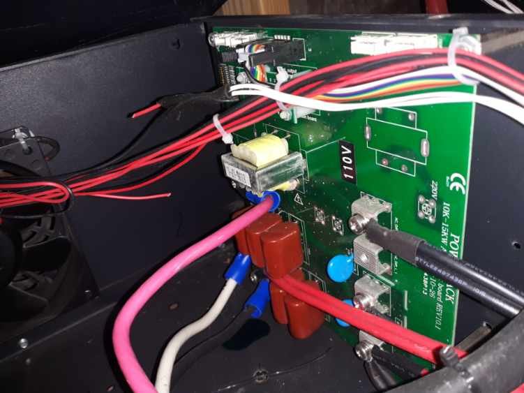
Here's a pic of the output board, doesn't appear to be completely populated, though I'm unsure exactly what is required for the GS board. I can add whatever needs to be added, and I don't mind making connectors for fans and what not. would really like to upgrade completely to the GS board and I'm quite comfortable working on this.
So a complete GS board upgrade (WiFi board + Control board) would completely remove the need for an output board. We have very limited stock of control boards right now...but we do have a few. You would need to get in contact with Sean for an upgrade kit of sorts...and I'm going to have get working on writing an upgrade manual sooner than I thought 😉
I've personally done a full GS upgrade on a 48v 15kw PJ inverter that had the twin short mainboards (and a 10.3 PJ control board)...but it sure isn't a job for the faint of heart! Parts were everywhere, and it looked like a total wreck there for awhile 😉.
Here's a photo of it after the upgrade:
FWIW I was quite pleased find that the PJ tranny in that inverter had a 32v primary--most PJ "48v" trannies seem to have a 36v primary, which gives you flat-topped AC waves with minimal load.
Your fully stocked bench sounds like it might come in somewhat handy...
I've had the whole thing apart and back together a couple times already, the only part i thought was a pain was trying to get the plastic standoffs under the main board to stay in place long enough to drop a screw in. My unit had a screw from the terminal strip (for the fans) rattling around when it arrived so I tore it apart for close inspection. While I had it apart I put some heatsink compound on all of the FET's and touched up some questionable solder joints.
My transformer is an asl6.5 with 36v primary unfortunately.
Now that I think about it, we did have to extend the transformer secondary wires to reach the GS control board...bit of a pain, especially as the trannies are wound with aluminum wire--which can't be soldered to without special equipment (that I don't have). But if you relish a bit of an electrical challenge...well...you can contact Sean and see about a full GS upgrade kit.
I should be a step ahead of the game in regards to the transformer wires as I have mine connected externally in an oil bath. Always looking for a challenge!
<a href="/monthly_2021_03/Resized_20200806_000637.jpeg.32bb532a2b20154d3ec316bba079f5aa.jpeg" class="ipsAttachLink ipsAttachLink_image"><img data-fileid="173" src="//forums.genetrysolar.com/applications/core/interface/js/spacer.png" data-src="/monthly_2021_03/Resized_20200806_000637.thumb.jpeg.3d7ce4e985d3081cddf150db55dd0cf7.jpeg" data-ratio="75" width="1000" class="ipsImage ipsImage_thumbnailed" alt="Resized_20200806_000637.jpeg">
<a href="/monthly_2021_03/Resized_20200805_004853.jpeg.26e61664017af7559859000d35042487.jpeg" class="ipsAttachLink ipsAttachLink_image"><img data-fileid="174" src="//forums.genetrysolar.com/applications/core/interface/js/spacer.png" data-src="/monthly_2021_03/Resized_20200805_004853.thumb.jpeg.b7e952d13a31a9cf56a3053462019706.jpeg" data-ratio="133.45" width="562" class="ipsImage ipsImage_thumbnailed" alt="Resized_20200805_004853.jpeg">


