PLEASE NOTE: If you had an account with the previous forum, it has been ported to the new Genetry website!
You will need to reset the password to access the new forum. Click Log In → Forgot Password → enter your username or forum email address → click Email Reset Link.
I moved my 15K to a new location to get closer to the battery bank and was rough handling it due to the weight and new location. When I reconnect the battery cables and turned the unit On nothing happened, I checked my connection and input voltage was 25.5 VDC and connect correctly. I removed cover and seen all 8 LED on mosfet boards lit and that was all. No LED's on any other boards,none on driver board,none on signal board,none on power source board,none on CPU board,none on I/C board,none on over load protection board and none on either of the main boards. NO LCD display on front panel, no fans,no alarms,no smell. Power save ON or OFF did not make any different. I checked DC amp draw off battery cable and got 0.01 VDC. I looked to see if any ribbons,cables or wires came off and could not find anything wrong. It is a OLD version with date on main board 2015/1/4 and mosfet boards also 2015. Where do I go from here? Thanks for the help.
Could you provide some photos of the setup / overview of the inside of the inverter?
2015 would be pre v4.0, so that is an oldie. Might be an oldie but a goodie if it's lasted you this long 😉
It sounds a bit to me like the cables going to the MOSFET boards might have come dislodged? Those provide power to the control board, without which it won't do anything.

A 2015 version with dual mainboards? Didn't know they did that back then. If there are led lights on the control board, that makes it a v7 or 8.
I too would like to see lots of pics of this inverter. Has it been updated?
First thing I would look at is the 10 pin ribbon from mainboard(s) to control board. Mainboard has power. Control board does not have power. Second thing is ground wire from control board to Neg battery terminal.
Thanks for the reply's and help.
Pic-0114-control board with ground wire to N battery terminal.
Pic-3136-Mos board V2.21 2015/6/15
Pic-5752- ribbon on right main board
Pic-5648- 2 ribbons on output control board
Pic-5632- ribbon on Left main board
Pic-4237-LED ON right mos board and ground wire to N terminal
Pic-4206- small pc board in the middle of the ribbon going from left side to control board. Question can I remove this and use a straight ribbon with no pc board?
Pic-4101-Note: LF 8K-15K Main V2.1 board
<a href="/monthly_2021_03/20210304_083136.jpg.0da924eb498ffe910325af667468fbc5.jpg" class="ipsAttachLink ipsAttachLink_image"><img data-fileid="141" src="//forums.genetrysolar.com/applications/core/interface/js/spacer.png" data-src="/monthly_2021_03/20210304_083136.thumb.jpg.a344748101d62d180382c1c263e99efa.jpg" data-ratio="75" width="1000" class="ipsImage ipsImage_thumbnailed" alt="20210304_083136.jpg">
<a href="/monthly_2021_03/20210307_110114.jpg.ec0cc2f4d90399976a1836b334ec22b2.jpg" class="ipsAttachLink ipsAttachLink_image"><img data-fileid="142" src="//forums.genetrysolar.com/applications/core/interface/js/spacer.png" data-src="/monthly_2021_03/20210307_110114.thumb.jpg.6f6871626b15992dbdb2cabdf85887f6.jpg" data-ratio="133.45" width="562" class="ipsImage ipsImage_thumbnailed" alt="20210307_110114.jpg">
<a href="/monthly_2021_03/20210307_105752.jpg.2666c8fdc5768d3a5378829d2cae0b26.jpg" class="ipsAttachLink ipsAttachLink_image"><img data-fileid="143" src="//forums.genetrysolar.com/applications/core/interface/js/spacer.png" data-src="/monthly_2021_03/20210307_105752.thumb.jpg.8a09aa733ccfe25ff1c30b87ce7899d7.jpg" data-ratio="75" width="1000" class="ipsImage ipsImage_thumbnailed" alt="20210307_105752.jpg">
<a href="/monthly_2021_03/20210307_105648.jpg.21c5e1bfb4b9765bd7279b836eafa13e.jpg" class="ipsAttachLink ipsAttachLink_image"><img data-fileid="144" src="//forums.genetrysolar.com/applications/core/interface/js/spacer.png" data-src="/monthly_2021_03/20210307_105648.thumb.jpg.fe3d8b0378a7f187c3f6c5b012bc4dd0.jpg" data-ratio="75" width="1000" class="ipsImage ipsImage_thumbnailed" alt="20210307_105648.jpg">
<a href="/monthly_2021_03/20210307_105632.jpg.88e5cffb10e3107d83b5cf6b3bd5c7c0.jpg" class="ipsAttachLink ipsAttachLink_image"><img data-fileid="145" src="//forums.genetrysolar.com/applications/core/interface/js/spacer.png" data-src="/monthly_2021_03/20210307_105632.thumb.jpg.4e06b70092911ffc6e75ff803160ad6d.jpg" data-ratio="75" width="1000" class="ipsImage ipsImage_thumbnailed" alt="20210307_105632.jpg">
<a href="/monthly_2021_03/20210307_104237.jpg.2c5cbb95abbabb09272dc63ae5ed51be.jpg" class="ipsAttachLink ipsAttachLink_image"><img data-fileid="146" src="//forums.genetrysolar.com/applications/core/interface/js/spacer.png" data-src="/monthly_2021_03/20210307_104237.thumb.jpg.5a394d4352119d8a022283bad82f5c39.jpg" data-ratio="133.45" width="562" class="ipsImage ipsImage_thumbnailed" alt="20210307_104237.jpg">
<a href="/monthly_2021_03/20210307_104206.jpg.45c19a4d3483eca4730f53c723cd98bb.jpg" class="ipsAttachLink ipsAttachLink_image"><img data-fileid="147" src="//forums.genetrysolar.com/applications/core/interface/js/spacer.png" data-src="/monthly_2021_03/20210307_104206.thumb.jpg.9f386643496dba63ac11729777080376.jpg" data-ratio="75" width="1000" class="ipsImage ipsImage_thumbnailed" alt="20210307_104206.jpg">
<a href="/monthly_2021_03/20210307_104101.jpg.d983f2be9413413fe7eee3b6c742c093.jpg" class="ipsAttachLink ipsAttachLink_image"><img data-fileid="148" src="//forums.genetrysolar.com/applications/core/interface/js/spacer.png" data-src="/monthly_2021_03/20210307_104101.thumb.jpg.1644b675839443bb05f374f11b9ba355.jpg" data-ratio="133.45" width="562" class="ipsImage ipsImage_thumbnailed" alt="20210307_104101.jpg">
<a href="/monthly_2021_03/20210304_083310.jpg.176ccc980e202ed489181d7a9a1d9a31.jpg" class="ipsAttachLink ipsAttachLink_image"><img data-fileid="149" src="//forums.genetrysolar.com/applications/core/interface/js/spacer.png" data-src="/monthly_2021_03/20210304_083310.thumb.jpg.e8bdb79a7dd6f33584db46222ea4c33c.jpg" data-ratio="75" width="1000" class="ipsImage ipsImage_thumbnailed" alt="20210304_083310.jpg">
Thanks for the photos. I see a few mods in there, gotta love it 😉. Ferrite core on the transformer wires to reduce no load current...ventilation hole in the back...
Looked a bit like the ribbon cables weren't plugged in fully, then I checked one of the boards I have and...I guess they look alright.
If you measure voltage from the battery negative terminal on the inverter, to the middle lead of the power switch, what do you get?
I'm trying to figure out where the power is stopping...especially if it worked fine before moving. Maybe just unplug and plug back in the connectors (particularly the front panel ones)?
Question can I remove this and use a straight ribbon with no pc board?
"First, do no harm"...
You probably could, but as I've never seen one of these before, I hesitate to recommend it. You could try a continuity check to verify that the pinout remains the same from end to end of a replacement connector if you want to. Getting pins wrong will almost certainly result in blowing up all the FETs, so...!
Leave it to Powerjack! Rather than make a long ribbon cable, they cobble up a 'jumper board" and plug two regular ribbon cables into it!
Still guessing, but did the inverter get dropped hard enough that it might have cracked the control board base? Its unlikely that both mainboards stopped sending power to the control board, so power must be getting interrupted after reaching the control board, but before it can do anything. Does the control board still seem solidly mounted? Or does it move or flex, perhaps at the corner where the two ribbons plug in?
Just my two cents. Sid's the expert.
So you have a rather "Old" unit there. It was the first round of the wide body 15kw units. I still have parts for those if you are interested just let me know.
Thanks for the photos. I see a few mods in there, gotta love it 😉. Ferrite core on the transformer wires to reduce no load current...ventilation hole in the back...
I get 0 volts because there is no wire on the center spade. I think the wire came off when it got dropped and was put on the wrong spade , see new pic. Where are the wires suppose to go. The switch is also bad,I believe the HOT lead should be on the center spade and the other 2 go with one on top terminal and the other on bottom terminal of the rocker switch of the same side of the switch. I sent Sean an email wishing to buy another switch and board that the lead plugs into that has the LED for Power ON,BTY ON, and ALARM.
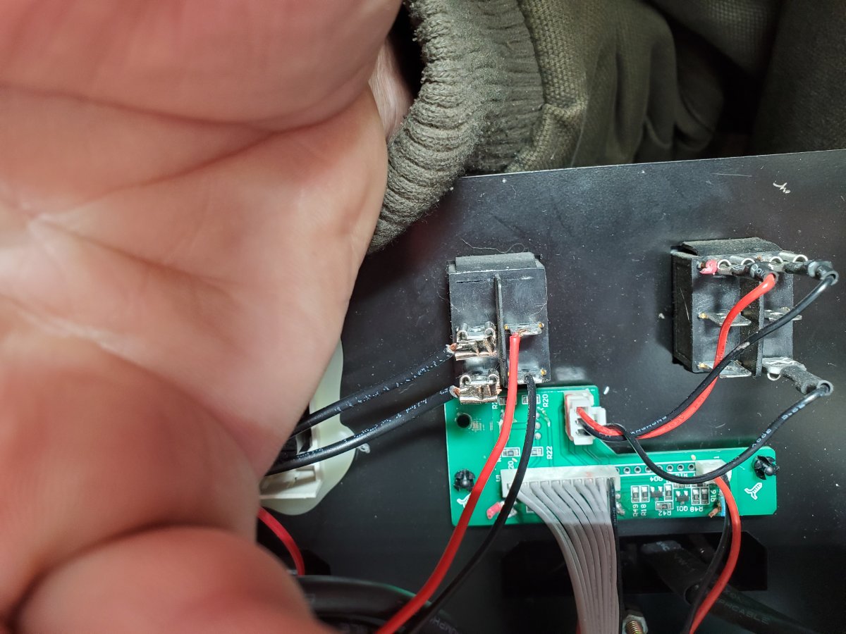
I think we found the problem; I do not think you need a new switch or board. I'd suggest gently tightening down the spade terminals' grip with a pliers before putting them back on (carefully--you don't want to squash them flat so they don't plug back in!) Bad connections due to loose (or corroded) spade terminals would cause frustrating reliability issues.
The switch pinout should match the little 3-pin connector. All that really matters is that the middle pin of the connector goes to the middle spade of the switch (pick just one side of the switch, ignore the other--it's a DPDT switch), and the other 2 leads go to the other spades on the same side of the switch.
If the switch is indeed bad, try moving the 3 wires to the other side of the switch. It's a low power signal, so I would be quite surprised if the switch is bad.
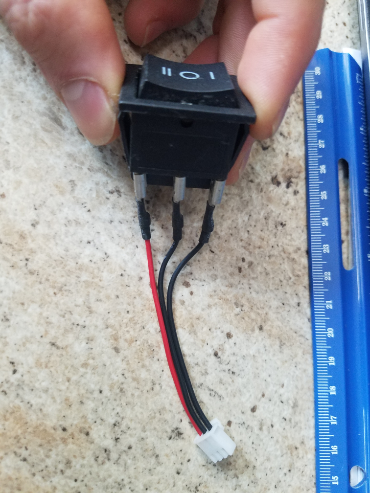
Here's a photo of an "official" PJ switch for pinout...please note that the 3 spade terminals on the other side of the switch are not connected.
17 hours ago, Sid Genetry Solar said:I think we found the problem; I do not think you need a new switch or board. I'd suggest gently tightening down the spade terminals' grip with a pliers before putting them back on (carefully--you don't want to squash them flat so they don't plug back in!) Bad connections due to loose (or corroded) spade terminals would cause frustrating reliability issues.
The switch pinout should match the little 3-pin connector. All that really matters is that the middle pin of the connector goes to the middle spade of the switch (pick just one side of the switch, ignore the other--it's a DPDT switch), and the other 2 leads go to the other spades on the same side of the switch.
If the switch is indeed bad, try moving the 3 wires to the other side of the switch. It's a low power signal, so I would be quite surprised if the switch is bad.
Here's a photo of an "official" PJ switch for pinout...please note that the 3 spade terminals on the other side of the switch are not connected.
//content.invisioncic.com/g308908/monthly_2021_03/image.thumb.png.0208c8c03c48f45aa30587c3ed27d0d4.png
I think that is his problem. The red wire also has to be on the side where the two black wires are or it does no good. The 10.3s I have they have changed the colors of the wires. They now use red, black, and white wires. They still use the same switch which is a standard double pole, double throw, center off switch.
Seems like it's always the little things that get you. Glad to see a simple (and cheap!) fix to what seemed a big problem.
I thank all of you for your help, it is up and running now with good output of just a small 1500w electric heater load on the 110 side outlet. 220 shows good voltage output on the LCD display. I will load pics tomorrow. Thanks again I could not have done it without all your help.
Glad to have been able to help. Seems that more often than not the issue isn't what we think it is at first without a lot of diagnostic info 😉
Kinda hard to remote diagnose something, even with photos.
But it's back up and running--which is very good.