PLEASE NOTE: If you had an account with the previous forum, it has been ported to the new Genetry website!
You will need to reset the password to access the new forum. Click Log In → Forgot Password → enter your username or forum email address → click Email Reset Link.
3 hours ago, Sid Genetry Solar said:By a couple frogs' hairs.
Perhaps a better way of phrasing the question:
What does the ASL number refer to? Is that merely a reference to the core? Wiring be damned?
3 hours ago, Sid Genetry Solar said:Is there room on the other primary lead?
There's no choke on the other lead. But the wire count appears to be the same... as i would expect.
I did manage to unwind the primary one turn to see what happens. Gonna make some measurements and maybe buy a choke since they don't seem to cost very much...
Fun to have a toy inverter to play with a bit...
1 hour ago, NotMario said:What does the ASL number refer to?
It refers to an entry in the PJ core size specification. Has nothing to do with the wiring specification, just a core size from the factory table.
1 hour ago, NotMario said:I did manage to unwind the primary one turn to see what happens.
Should have plenty of wire for 2 turns on the existing ferrite now?
16 hours ago, dickson said:The new AMG transformer will do 1/4 or less of the 8kw advertise .
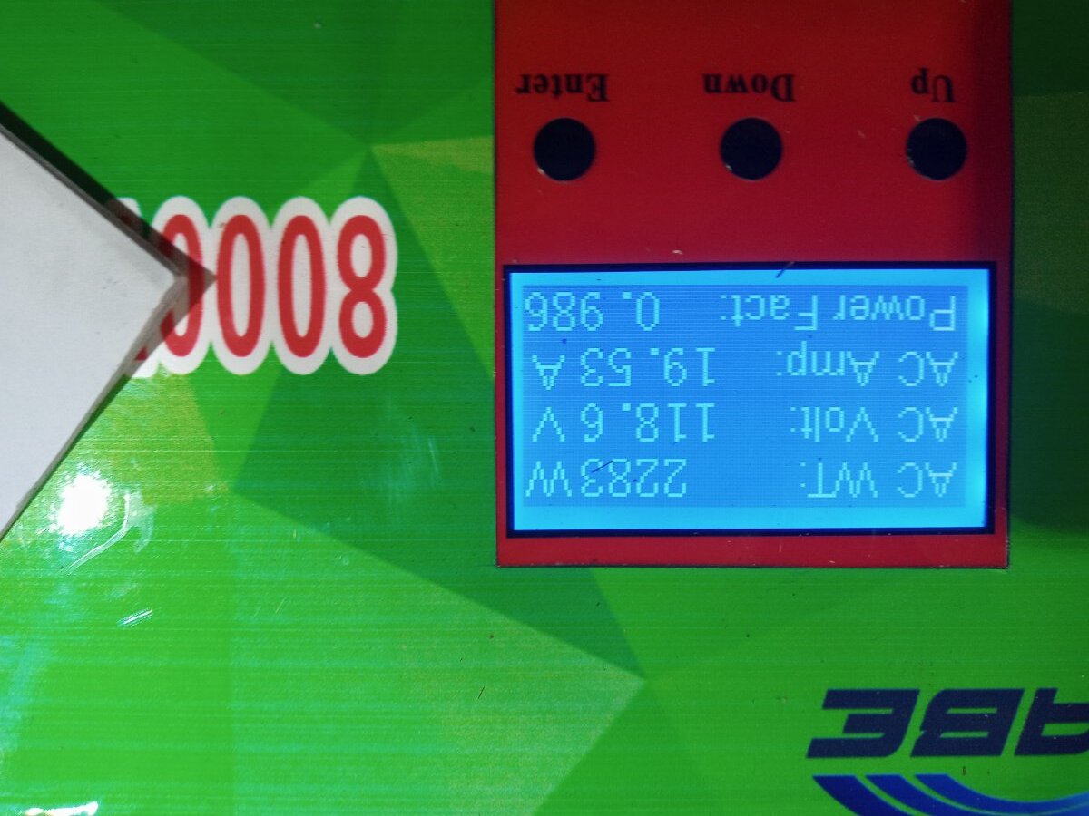
When I load tested my AMG "8000" inverter, I ran a space heater on L1 and a heat gun on L2 for a total of 27A or 3100W continuous. They advertise it as 4000W. It didn't shut down
3 hours ago, Sid Genetry Solar said:Should have plenty of wire for 2 turns on the existing ferrite now?
Ah, no no, you misunderstood.
Plenty of length to work with. No issue there.
Rather, the wire(s) is way too thick to wrap around the ferrite twice. I will need a bigger ferrite to do that.
11 minutes ago, RobertM said:When I load tested my AMG "8000" inverter, I ran a space heater on L1 and a heat gun on L2 for a total of 27A or 3100W continuous. They advertise it as 4000W. It didn't shut down
I don't think there's any consistency in what the inverters will do. Seems to be pure luck. You and i got lucky...
My 3 years old PJ 8kw has 40 FETs and can do 3500 watts with ASL4.0 transformer .
wow, so increase in the number FETs - this one has 24 if I have it right ;
Ok, "relative to the center tap" puts more light on that 240 and phase topic ;
Sid,think I have one of the top before tearing it up - look in a minute ; This is the production machine, so all back together and going ; adding pic of the day here too on load ; There is a 110v sticker on top somewhere on the topside ; Don't see the top - will pull the lid and go in there again tomorrow ;
Thanks everyone ; Believe it's time to gather stuff and push it on up in a load test also ;

7 hours ago, NotMario said:
I don't think there's any consistency in what the inverters will do. Seems to be pure luck. You and i got lucky...
Maybe you're right. PJ inverters are odd, but mine cost only $399, and I'm using it. It kept running when the ambient temperature was 115° F, although it was only powering 500W, with the fan running loud. I'll admit that my entire solar power system (800W of panels and 3500 watts of battery storage) is 3rd world.
Should have plenty of wire for 2 turns on the existing ferrite now?
To clarify, when you say 2 turns...
You mean each wire would go through the center the same direction 3 times? (meaning it would wrap around the toroid two times)
From the factory... the wire goes through the center 2 times. In this case, it is utterly full.
You mean each wire would go through the center the same direction 3 times? NO
From the factory... the wire goes through the center 2 times. In this case, it is utterly full. YES
Ugh terminology differences.
Refer here:
<a title="
Link to post 37870 by user sid-genetry-solar
"Two full turns"
I'd interpret that as wrapping the toroid twice.
If what you say is true, one less than twice would just be a wire going through the center, without wrapping it at all... essentially a waste of a choke?
Surely the factory would never do that...
Well, so technically @dickson is correct...
Because from a magnetics standpoint, putting the wire straight through the center IS a "1x core voltage". Because technically, the wires will make a circuit on the other end, through the load (or whatever). I actually do this for transformer testing to determine the "core voltage" of a toroid of unknown specification (though technically the core works in magnetic fields, not electrical voltage!)
Making a loop around the actual core (with 2 passes through the center) will give you "2x core voltage"--because technically there's 2 total loops around the core. One on the core, the other through the load...
But @notmario understood what I meant 😉. Partly why I kept stressing "full" turns...though I now realize that my terminology was a bit confusing...
So yes, the factory normally does 2 passes through the center, with one visible loop on the outside of the core. I find that 3 passes through the center (2 visible loops on the outside of the core) to be "best"; beyond this, you really don't get much improvement.
Aha, thanks for the lesson, friends.
Ok, so i will get a bigger toroid (or two...) - there is absolutely no hope of getting three passes through the center on this one.
For my sanity, i cross-referenced against the GS - which also has only 2 passes through the center (on 4 distinct toroids...) Wasn't at a good angle to see all 4, so maybe the one i couldn't see had 3 passes. IIRC, that one was a lot busier than the others...
For the record, current no-load current (u-power...) is 0.96A @ 27.3v.
For my sanity, i cross-referenced against the GS - which also has only 2 passes through the center (on 4 distinct toroids...) Wasn't at a good angle to see all 4, so maybe the one i couldn't see had 3 passes. IIRC, that one was a lot busier than the others...
Hmm....they SHOULD have 3 passes through the center each...
For the record, current no-load current (u-power...) is 0.96A @ 27.3v.
actually not bad...but you should be able to get it down to 750mA or so I would think.
my entire solar power system (800W of panels and 3500 watts of battery storage) is 3rd world.
Yeh well, if it keeps the power co away and none of their "ready to serve" fees before a single kw, then it is beautiful - praisetherays ; Otherwise, just keep adding piece at a time as funds arrive.
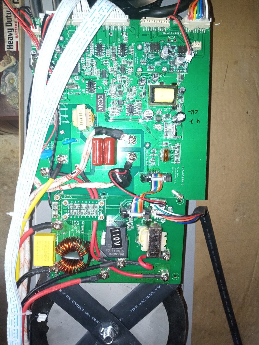
So from that photo, I can be reasonably certain that the control board is regulating from 120v.
<fileStore.core_Attachment>/monthly_2022_10/Untitled.jpg.7b18eda4c4c1886046efc7d076081772.jpg
Firstly, the "110v" sticker on the lower right--though obviously that can't be used as a "definite".
If you measure 120v across the 2 circled screws, then we can confirm that the inverter is regulating from 120v.
Notice on the top left circled area, that looks like 2 separated wires--though it does appear that they are crimped to the same end terminal. Like I noted above, they'll be aluminum--so if you split anything apart, you'll have to have crimp terminals and tools to make a good connection.
I would assume that one other "white" transformer wire goes directly to the front panel?