PLEASE NOTE: If you had an account with the previous forum, it has been ported to the new Genetry website!
You will need to reset the password to access the new forum. Click Log In → Forgot Password → enter your username or forum email address → click Email Reset Link.
On 10/3/2022 at 10:27 AM, Sid Genetry Solar said:you'll have to have crimp terminals and tools to make a good connection.
I would assume that one other "white" transformer wire goes directly to the front panel?
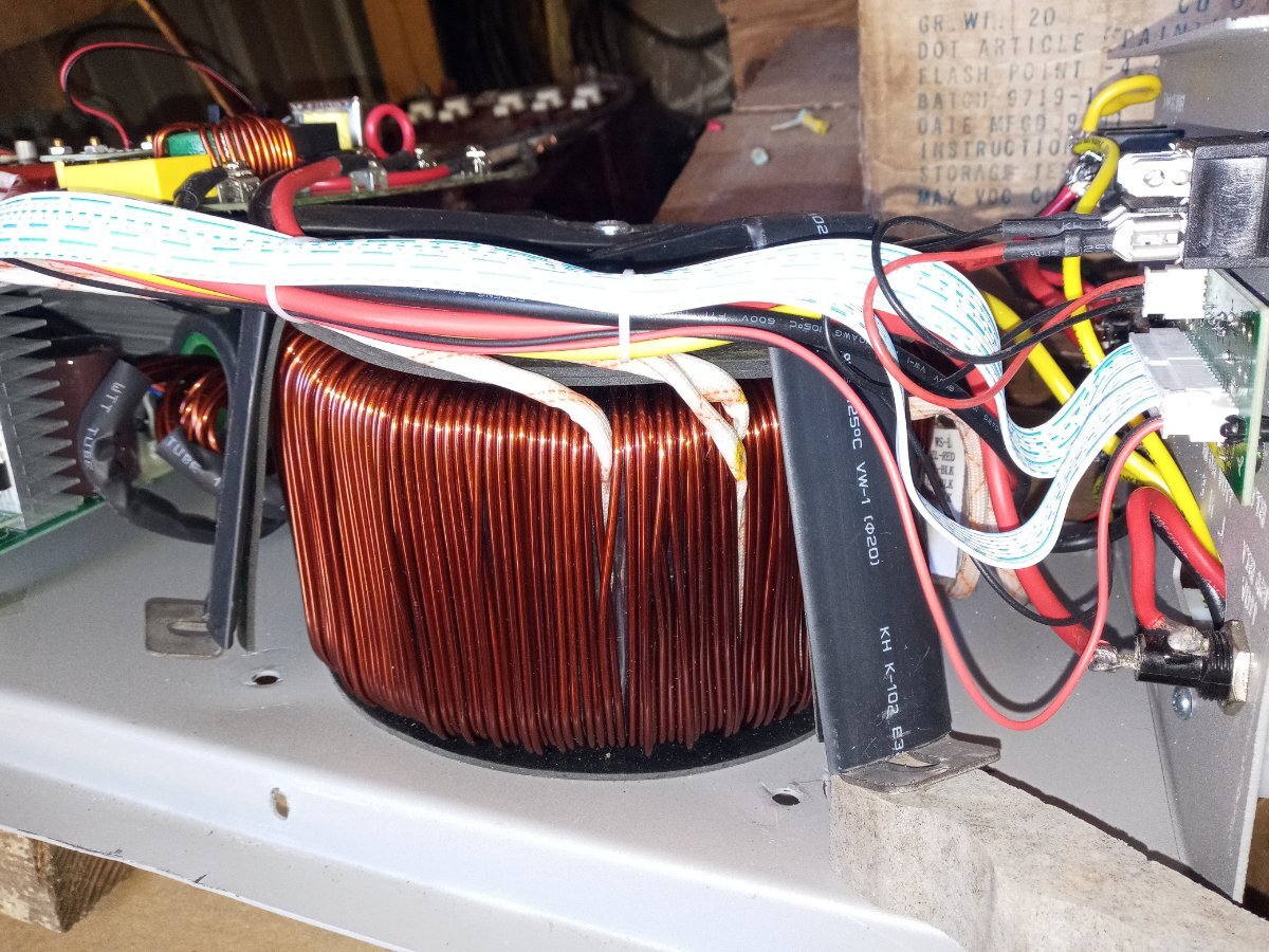
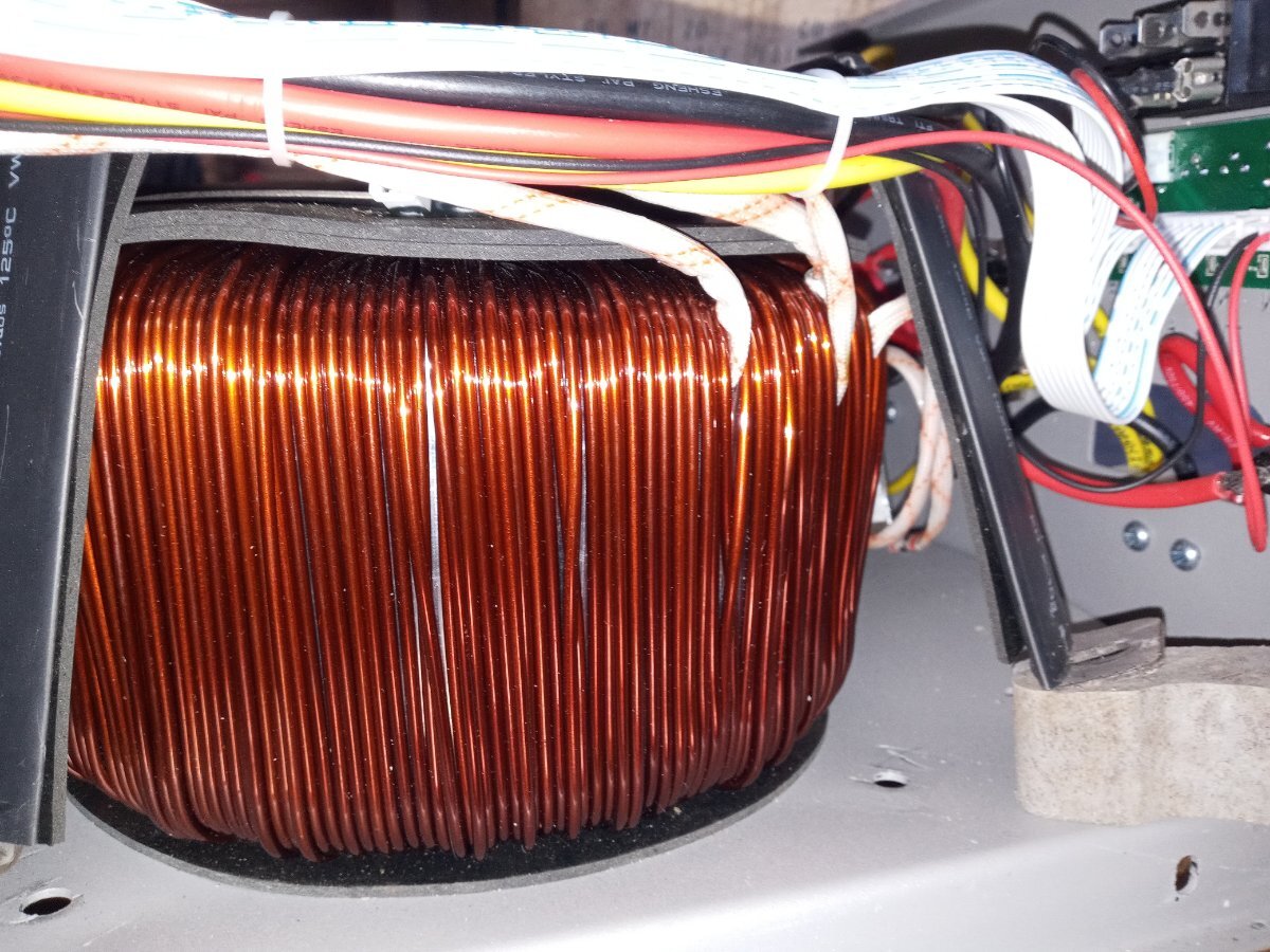
Have a hydraulic crimper ; "white" wires routing has been in question - disappear in under one transformer holddown strap ; Been meaning to investigate and liberate when making holes in the disc on top and raising transformer some to increase airflow - only idea so far ; Have now done half and reassembled as oem on the airflow ; Pics of wires attached - two go in under the outer (primary?) winding and one comes out and goes to panel fuses then to red or line of the 120v outlets ; Second was supposed to show the loop and attach to panel fuses. lol ;
Am reminded by pics now, all FOUR go inside outer winding....
//content.invisioncic.com/g308908/monthly_2022_10/20221004_123831.thumb.jpg.647349038566b13c67b1f56a2f75f447.jpg
//content.invisioncic.com/g308908/monthly_2022_10/20221004_123725.thumb.jpg.6286956ffc92cce2c15980c0607aa067.jpg
<img class="ipsImage ipsImage_thumbnailed" data-fileid="1714" data-ratio="109.66" width="321" alt="image.png.0eea04950ed5f8a234d50bb93461fbdb.png" data-src="/monthly_2022_10/image.png.0eea04950ed5f8a234d50bb93461fbdb.png" src="/applications/core/interface/js/spacer.png" />
Well, so this isn't an "AMG" winding spec tranny, and it does appear at first glance that the 2 output phases are different winding thicknesses. I would expect these 2 middle ones to be the "junction" between the 2 120v windings.
If you feel through the white protective covering, do you find that some of the white covered wires have 1 wire inside, but others have 2 wires?
You would also want to check the voltage from L1 - N and L2 - N at no load, and see if they are basically the same. (PJ is known to get these several volts apart, which would be rather problematic for any "120v single phase" rewiring attemps.)
On 10/5/2022 at 8:22 AM, Sid Genetry Solar said:Well, so this isn't an "AMG" winding spec tranny,
PJ is known to get these several volts apart, which would be rather problematic for any "120v single phase" rewiring attemps.)
Aha ; And I have noticed voltage differences at one point ; LCD is always 119.5 and never lower than 117.5 - other line showing 111.x on my dmm while agreeing with LCD on other line - pretty wild ; So that agrees with and reinforces your take on the "AMG and-or able to be rewired"
Thank you again and one day I will have a Genetry Solar 12k....
PS I have not tried to adjust AC voltage on the panel as I am thinking it would only be the one line and has no feedback from other line ;
1 minute ago, praisetherays said:PS I have not tried to adjust AC voltage on the panel as I am thinking it would only be the one line and has no feedback from other line ;
So there isn't any magic here...the transformer is always a fixed ratio. Adjust the voltage one one line, and the other line will follow.
It is not possible to separately regulate different taps on a single transformer. However, it can "appear" that way in a sense...because only one (L1 - N) is regulated, the other one (L2 - N) will go wherever it does, based on transformer losses and load.
6 minutes ago, Sid Genetry Solar said:So there isn't any magic here...the transformer is always a fixed ratio. Adjust the voltage one one line, and the other line will follow.
It is not possible to separately regulate different taps on a single transformer. However, it can "appear" that way in a sense...because only one (L1 - N) is regulated, the other one (L2 - N) will go wherever it does, based on transformer losses and load.
Ok, makes sense ; Well, is the 119.5 to 111.x difference a reasonable possibility based on all this ?
3 minutes ago, praisetherays said:Well, is the 119.5 to 111.x difference a reasonable possibility based on all this ?
It almost certainly results from a sloppy winding specification. Technically, you could "add a few turns" of wire to the winding that's low, and bring it up to match. But it depends how deep you want to get into the inverter!
It almost certainly results from a sloppy winding specification. Technically, you could "add a few turns" of wire to the winding that's low, and bring it up to match. But it depends how deep you want to get into the inverter!
Already deeper than the plan, lol ; Do like the separate boards and sockets for sub-boards - world of difference from that reliableelectricWRELZB? 3000 ; the mosfet control board is soldered - never again ; So it is all relative, I suppose ;
If you really want a single-phase 120v output inverter, it's possible with the current unit you have. You'll just need to get the secondaries to match voltagewise (and split them apart). You'd really want to have a variac for this sort of work though.
Can't guarantee that going single-phase will fix the issue, though...it sounds more like a software/drive issue.
It almost certainly results from a sloppy winding specification. Technically, you could "add a few turns" of wire to the winding that's low, and bring it up to match. But it depends how deep you want to get into the inverter!
My 15kw PJ is 48vdc and L1 is 115vac and L2 is 105vac and I add 15 turns to L2 to increase L2 to 116vac . I do not know how many turms to add to L2 if 24 vdc transformer .
I do not know how many turms to add to L2 if 24 vdc transformer .
Does not make a difference.
Do like the separate boards and sockets for sub-boards - world of difference from that reliableelectricWRELZB? 3000 ; the mosfet control board is soldered - never again
That reliableelectricWRELZB? 3000 is a lot more reliable than the 8kw PJ inverter and has good review and youtube show how to solder the mosfets .