PLEASE NOTE: If you had an account with the previous forum, it has been ported to the new Genetry website!
You will need to reset the password to access the new forum. Click Log In → Forgot Password → enter your username or forum email address → click Email Reset Link.
The German electrician said I could parallel 3 of the Siemens 160 Amp NH fuses but would need cable to support 480 Amps then..
You can use two awg 4/0 cables to connect the 3 Siemens 160 Amp NH fuses IT is too expensive to use one 480 Amps cable .
my 5000-watt inverter will have 2 4/0 cables one to each terminal >>>> 2 negatives and two positive 4/0 cables, ((two positives 4/0 cables, two negative 4/0 cables)
A 5000-watt inverter if it is a powerjack will not output 5000 watts . One positives 4/0 cable and one negative 4/0 cable will work . The GS6kw inverter only has 2 terminals and Sean use one positives 4/0 cables and one negative 4/0 cables . Even the GS12kw inverter has only 2 terminals . The GS12kw should have two positive terminals and 2 negative terminals to carry 12000 watts . I use two 4/0 positive cables and two 4/0 negative cables on my powerjack 30kw .
The GS12kw should have two positive terminals and 2 negative terminals to carry 12000 watts .
yes I think from the electrical folks I have talked to >>>> that two terminals for positive and two terminals for negative is better to distribute the amperage...
the 5000-watt inverter has 2 positive and 2 negative terminals....it is 24-volts but has shown to run the full 5000-watts but it is not a Powerjack.
I have a 15000 watt Powerjack 24-volt inverter that has 2 positive and 2 negative terminals to connect to the battery also ..
Yes you need 2 positive and 2 negative terminals. Powerjack web page say for any inverter 24vdc and over 4500 watts must have 2 positive and 2 negative cables . Wes the tech guy on Youtube say the awg 4/0 cable is cool at room temperature otherwise the cable is too small . I am still assembling my battery .
the electrician from Germany said to use 24 volt or 48 volt in the fuse sizing calculations
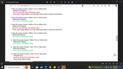
so 6000 watts divided by 24 volts equals 250 Amps
then upsize the fuse by the 1.25 factor equals 250 x 1.25 = 312.5 Amps for the 24 volt 6000 watt inverter
5000 divided by 24 x 1.25 = 260 Amps >>> (((((but the inverter actually says 6000 watts... with a 12000-watt peak (although it will never do that)))))
the closest I have is 355Amp NH fuse, >>>>..so I will have to find a more appropriate sized fuse for 6000-watt inverter loads...
I also note that LiFePO4 batteries are tested for energy at the factory and not Ah.... according to "Average Joe's" YouTube video I was watching...
energy or power is measured in Watts Wh (hope I got that part stated right)????
I think Andy was also showing that same style of measurement on his "off-grid garage" YouTube videos with the LiFePO4 battery testing
seems like learning the correct jargon and expressing things correctly is always a learning process when it is not your 1st or main profession....
You post the closest I have is 355Amp NH fuse, >>>>..so I will have to find a more appropriate sized fuse for 6000-watt inverter loads.
The fuse is to protect the cable . One AWG 4/0 will carry 230 amps . A 6000 watt 24 vdc inverter will produce 313 amps need two AWG 4/0 cables that can carry 460 amps . A 355Amp NH fuse can be use to protect the 2 cables . A 5000 watts 24vdc produce 260 amps and if you use 2 AWG 4/0 cables then a 355Amp NH fuse will also protect the 2 cables .
@dickson yes>>>> the 24-volt 6000-watt inverter has 2 positive and 2 negative posts for connection to the battery....
so headed in the right direction.... thanks for the replies!
when I asked the reason for the 2 posts for negative and 2 posts for positive on my 15k 3pc 24volt inverter .... seems like sxx(don't mention his name) 🤔🤔said I did not need to hook to both as they are connected internally to the same place....
but now I think it would be a lot better to have 2 4/0 cables to positive and 2 4/0 cables to negative to carry the heavier loads and have less heat generated...(each 4/0 copper connected to separate terminals on the inverter)
Powerjack web page say the 2 posts for negative and 2 posts for positive on your 15k 3pc 24volt inverter is needed to have 2 4/0 cables to positive and 2 4/0 cables to negative to carry the heavier loads and have less heat generated...(each 4/0 copper connected to separate terminals on the inverter) .
I have to wonder if some people purposely give the wrong advice or they lack a complete understanding of the requirements for safely operating high loads on a DC inverter...
names purposely withheld and it is not Dickson either....
I bought a 3-pole disconnect for the NH-type fuses that should arrive soon....
the disconnect is rated for DC....
hopefully, never blow the Dc fuses but hey are there for safety reasons.... as catastrophe conditions....
