PLEASE NOTE: If you had an account with the previous forum, it has been ported to the new Genetry website!
You will need to reset the password to access the new forum. Click Log In → Forgot Password → enter your username or forum email address → click Email Reset Link.
So a Genetry Solar customer recently asked me if I could take a look at their Magnum 4448 to try to figure out why it often just won't turn on anymore. (Reportedly if it turns on, it will run just fine.) The unit was manufactured in 2009--so being 13 years old gives it somewhat of an excuse.
At any rate, though, I took it as an opportunity to "see what's inside" a 4.5kw inverter that sells for over $2,000. Worth noting, however, that the label says it was "Engineered and Manufactured in the U.S.A." So that price point is actually quite an accomplishment--that is, assuming they're still manufactured in the States!
Checking online, the newer units no longer say anything about "U.S.A"...they instead say, "Designed and Manufactured by Sensata Technologies"--which has global presence, with manufacturing facilities all across the globe (including several in China). So....you can pretty well strike Magnum off the ever-dwindling list of U.S.-made inverters.
Two things the customer DID note were:
- An HE washer absolutely refused to work with the Magnum 4448. (Interestingly, I found another forum post showing extremely distorted output waveforms with a washing machine load.) Makes me feel not so bad about some HE washers not liking GS inverters--though I really want to find out exactly why. (Unfortunately, I haven't been able to gather enough diagnostic info at the current time.)
- The Magnum 4448 also could not start an 18,000btu window A/C. (A GS 6kw reportedly starts it without hesitation.) I did a tad bit of research online, finding that an 18,000btu 240v A/C likely has an LRA of ~46A.
- What I found interesting was that the Magnum 4448 spec very curiously does NOT list the high surge ratings in watts! They're listed in Amps instead. Which is a clever marketing trick (if I say so!) that proves basically nothing: If you've got 46A @ 240v, that's 11kw. But if you have 46A @ 5vAC, that's a measly 0.2kw...let me tell you, an A/C compressor will recognize the difference between the two!
First challenge was getting the inverter lid off. With every screw being a Torx, that was mildly complicated--especially by a few sneaky screws that had basically no clearance, making it almost impossible to use a small bit with an extension on it...

Digging into it, one of the first things I noticed was the stack of 10 ferrite beads on one of the transformer leads. Umm...maybe someone should tell these guys they can use just a single ferrite with a couple turns of transformer wire around it?? Might be a bit cheaper 🤪.
On the left side of the transformer, you can see several yellow wires. There's a very heavy (0AWG?) black wire barely visible between/underneath: that is the main transformer power wire. These yellow wires are a bit of a "shunt" over the said main wire, bypassing a small amount of the current through the blue current sensor--this would serve as their "FET current limit" sensing circuit.
I'm not saying this is a poor design. However, on GS inverters, we've gone with a copper busbar simply due to the fact that that is CNC machined--and as a result, in a production environment, each unit should be very similar, without large variances. The issue with hand-cut and hand-crimped wires (especially in high-current environments such as these) is that any length variance will result in a noticeable (if not significant) adjustment in the current sensing functionality.
Perhaps this is why you can see a blue potentiometer on the other side of the board near the blue current sense transformer on the other side of the control board 😉.
Another discovery I made: the Magnum MS4448 manual lists the battery voltage range as "36.0 to 67.6 VDC", absolute max 68vDC.
OK, so then what's this mean on the main DC bus filter caps??

Either I might need to get some glasses, or else that seems a bit lower than the rated max of 68v.........
Digging a bit further, I became rather suspicious of the main MCU on the control board (which has a PLETHORA of analog clutter all around the board! If I designed a control board like this, it'd be less than half the size after throwing out all the junk!)
At first glance it looked awfully similar to the MCUs used on Power Jack v3.0 control boards--as well as any other Chinese inverter brands that reportedly copied an older Xantrex inverter design (Must Power, Felicity Power, even Aims, Sungold Power, etc.)
And you know why? Because IT IS THE SAME PROCESSOR! Same extremely weak 8-bit 68HC08-based processor.
OK, OK, this was manufactured in 2009--I know that MCUs have made scary leaps and bounds in technology in the past 15 years, but I mean....!
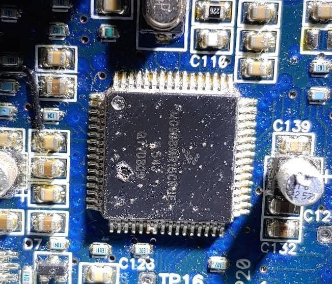
A Freescale MCU (this means this has to have been >2004, when Freescale branched out from Motorola, who invented the 68HCxx family), with a part number of MC908MR16CFUE.
The PJ v3.0 control board I have has a part number of MC908MR32CFUE--identical processing power, but with more FLASH memory!
somewhat comically, this extremely outdated processor sells for about $25/ea. You can buy a Taiwanese ARM-core 32-bit MCU with leaps and bounds more functionality for $2.20/ea!
Another observation I made was that the main switching FETs are SMT (surface mount) TO-263 package. Obviously, these can't generate much heat, as it's very difficult to dissipate heat from a package that isn't designed to be mounted on (or to) a heatsink!
There's also only 3 per quadrant of the H-bridge. This would definitely explain the lack of surge ability...GS6 inverters have 6 per quadrant.
And yes...the inverter will not turn on. Pulls ~42mA @ 48v, doesn't do anything. Customer was suspecting the control board to be at fault--but after some measurements with my DMM, I'm pretty sure the fault lies with the SMPS on the mainboard. There's no power on any lead going to the control board--of course it won't turn on!
Well, OK, yes, there's 48v battery voltage on one lead--but I'm pretty sure that'd be for battery voltage feedback, not a power source (as there's no power supply visible on the control board). And there's also 0.6v on another lead--which appears to go directly to the power button. This is where I'll start diagnosing: is it a bad power button? (Don't think so at this point!) And...is that 0.6v supposed to be 4-5v and is shorted out by a diode junction?
Obviously, if someone knows the answer, they're more than welcome to tell me 😉. Otherwise, I'll plug along with this for a bit, and see if I can figure it out without spending too much time on it.
Finally got the control board out to examine the SMPS, and noticed R53 looked a little strange. Kinda like it'd been blown out? I mean, a Sharpie marker could look like this, but it felt dimpled. Worst part is, I had no idea what value the resistor was.
A voltage measurement showed battery voltage on one side, but no voltage on the other. Hmm...that doesn't prove a faulty resistor (could be a shorted circuit on the other side, but...)
Broke out my soldering iron, and very soon discovered that R53 comprised of TWO 2512 SMD resistors stacked right on top of each other. The second resistor had a value written on top: R200. (0.2 ohms.) This label very soon disintegrated as I tried to remove the second resistor--which revealed that the second resistor was also (unsurprisingly!) blown.
So I replaced R53 with a 1-watt wirewound 0.22-ohm resistor from my junk box.
...wait a minute, now the inverter's basically a dead short to the DC battery input! (Power supply current limit set to 1 amp.)
I measured 0.8v across the mainboard DC potential. A few more quick checks showed that the main SMPS FET is shorted--as there was only 0.1v on the gate, and it was shorted on (right below the blue resistor).
............
Some time later, after disassembling the inverter so I could get to the bottom of the PCB...and getting out my giant 200W soldering iron (giant to me, but boy does it make stuff happen!), it was time to pop the blown FET off the board.
Sure thing, the FET was a dead short. I didn't have an exact replacement for the (IR)FS33N150 FET, so I scabbed in an IRF640 (200v!) pulled from a PJ board. Reconnected my 0.22-ohm resistor (as well as the electrolytic bus cap I'd pulled out to access the FET leads).
Well, now it doesn't pull 43mA, it pulls 8mA @ 48v--but still doesn't work.
Unfortunately, the Magnum 4448 mainboard appears to be a four-layer PCB. This explains how they can make their particular topology lineup work...inner copper layers. But it also renders signal tracing basically impossible--and I'm unable to figure out where the SMPS FET gate goes. (I measured ~2v on the gate with 48v input, and 0.39v at 24v input. Unsurprisingly, at 48v, the IRF640 FET gets gently warm as a result. I did try "popping" the transformer with a 100-ohm resistor from ground to the FET heatsink, to see if the SMPS circuit just needed a "startup"--but alas, nothing happened.)
I can't really do any further diagnostics on the SMPS, as I can't trace the circuit due to the 4-layer PCB. So...can I just power up the electronics and have it "work"?
Looking a bit further up the mainboard, I noticed a part marked "U4". Looks an awful lot like a voltage regulator--and after a lot of digging around online, I managed to find the datasheet it corresponded to. The only visible marking was "50A-5G". Some web searches didn't turn up much usable info--but one of the results was a datasheet that had the clue:
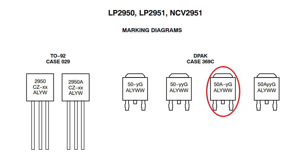
Bingo: 5v linear regulator. So now that tells me where the control board gets 5vDC from--as well as a hint as to where the main power rail is. (I kinda suspected from a diode right into a big cap on the output side of the SMPS transformer.) Now, what voltage is the power rail supposed to be? I don't have a clue--but as FETs are being driven, I'm going to assume closer to 12v.
Did some poking around and testing...took a bit of courage to turn up the current, but if I power the main power rail cap from 12v, it runs ~180mA without the external screen plugged in. With said screen plugged in, it runs closer to 250mA--but it DOES turn on.
Worth noting that the power button is useless when backpowered like this. I am suspecting that a chip I can't find a datasheet for on the mainboard, is responsible for the power control. It's a Freescale chip (by logo), but I can't get a part number off of it that makes sense, thanks to the conformal coating.
I've half an idea to try to backpower it with an XL7015 buck step-down board (set to 12v) and see if it'll fire up and run the transformer...unfortunately due to the 4-layer PCB, I really can't trace out the rest of the SMPS control circuit.
Cool, this is the inverter that I was complaining about surging with the oven (although mine are a little more recent)!!
Neat to see you tearing into it. I get the feeling that magnum is either working on outsourcing, or going out of business. Thanks for sharing!
Just for the record, here's the FET layout--I had to take the mainboard out for tweaking, so I guess it's all out there.
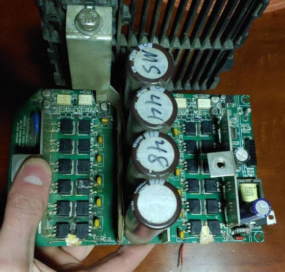
Notice the matched FET driver setup--each one of those white things is an optoisolated FET driver. Looks like they might be doing totem pole FET drivers after; I haven't traced the circuit (no interest or need to).
You can see the hacked-in IRF640 on the bottom right, with the scabbed in 0.22-ohm wirewound resistor right below the tall cap.
You also might notice that one of the FETs looks strange...3rd up from the bottom on the left column. There was a big "blob" on top of it (I scraped it down out of curiosity) with a corresponding big melted spot in the rubber that goes on top of these FETs.
Also you can see that there's probably 6 FETs/bank--I just didn't see the rest of them. And no, I haven't tried to figure out if I can read a part number off of them. That conformal coating is serious stuff.
Chip at the top right corner is the "50A-5G" linear voltage regulator. And you can see the little red wire peeking out from under the board--that's the "+12v power line." It might have originally run on +15v, I don't know...
At this point, I'm suspecting that the damage to the SMPS is beyond reasonable repair--unless I had a full schematic of the circuit. And even if I did, I might not be able to source ASIC parts (like I'm suspecting the chip near the SMPS [not visible in this photo] might be). I quickly threw together the basic SMPS forward converter drive schematic as I understand it to be in the 4448:
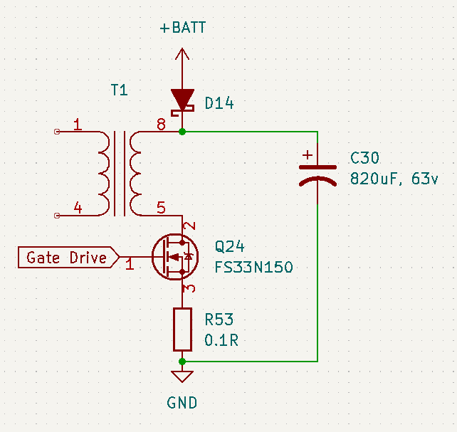
Here's the problem. R53 was blown open-circuit -> suddenly there is no reference to hold Q24 down.
I've checked (and confirmed): Q24 is a complete dead short, all 3 leads.
This means that the "Gate drive" circuit was shorted to battery voltage through Q24, T1 and D14--and almost undoubtedly damaged as a result.
This explains the 48mA draw (through the gate drive circuit) that vanished when I replaced the Q24 and R53--it fell to a more expected 8mA.
There's about 2 SMD resistors on the other side of T1 (closer to the mystery IC) that appear to be damaged. And by "appear to be damaged", I mean, "marking is missing/flaked off the top." Which makes replacing them basically impossible--and as a result of the damaged gate drive circuit, it's basically game over for SMPS as it stands.
So I can't quit on something........
I did some poking around, putting a current-limited 12v on what appears to be the output of the little SMPS forward converter. After some false starts, I found that the control board is actually pretty power hungry, pulling a happy 150mA @ 12v just to turn on. With the external "remote" connected, it pulls over 250mA.
Anyway, I ended up soldering a wire to the positive side of the cap on the output of the SMPS forward converter, so I could reinstall the boards back in the Magnum inverter--and still provide power to the DC bus.
A few tests later, I ended up finding that curiously, with the control board reinstalled on the mainboard, apparently the half-dead SMPS on the mainboard was trying to turn on?? Suddenly it was pulling a pretty good (1A) load, causing my power supply to current-limit at 12v...and the half-baked-in IRF640 was getting pretty hot. As a solution, I completely removed the IRF640 from the mainboard--I was not planning to use that SMPS any further, as I can't determine the extent of the damage (due to unreadable IC part numbers, and the 4-layer PCB making circuit tracing impossible).
Next, I pulled a generic XL7015 high voltage buck converter board (from AliExpress) out, and used alligator clips to wire things up for a quick test. I set the XL7015 to 12v, as a safe guess...this making it so I could run the main battery terminals to the necessary ~48v, but run the DC control board bus at 12v (as it would be fried with 48v.) The unit powered up fine--well, it did have a complaint:
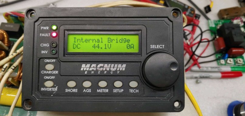
Hmm. This could mean one of 2 things.
As the unit used a forward converter SMPS, this means that (like PJ inverters), it could be using separate taps on the SMPS transformer for high-side FET gate drives. If this was the case, I was basically dead in the water--as there would be no simple ways around this problem (save fixing the actual SMPS). Yeah, isolated DC-DC converters would do the trick, but I didn't have any...and they're rather pricey anyway.
The other option was that perhaps the 12v I'd set the DC bus to, wasn't high enough. Most FET drivers have an "undervolt lockout", a threshold voltage below where they'll refuse to operate.
I pulled up a datasheet for the A316 FET drivers:

umm...yeah. Looks like 12v won't do!
I adjusted the XL7015 to 15v, and tried again...
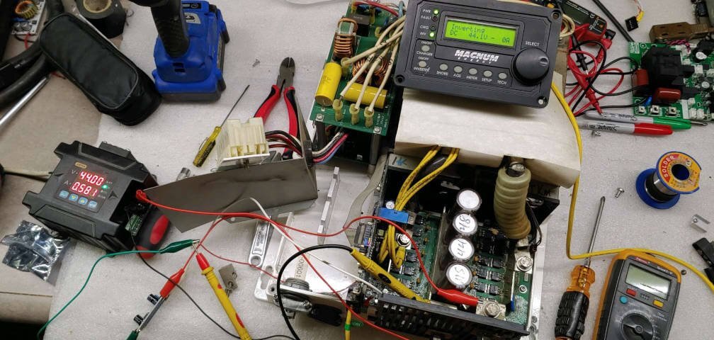
Well, would you look at that: it actually fired up! (XL7015 board visible at the lower left, with the red, white and green alligator clips on it.)
I guess I've started taking for granted the almost silent idle of a Genetry Solar inverter--this Magnum greeted me with a very pronounced AC buzz, as well as a hissing buzz from the stack of chokes. But the idle current of ~24W was right in spec with the manual.
(I can recall those first few times Sean or I would power up a Genetry inverter, and after not hearing anything, find ourselves wondering if it was working--until we found 240vAC one way or another and realized that it was actually on, and working perfectly!)
After wiring the XL7015 board in for permanent (plus adding a few protections to it...reverse polarity diode & soft-start resistor, both for transient voltage protection), I did test the inverter with a 300W load (about the max my bench supply would do):
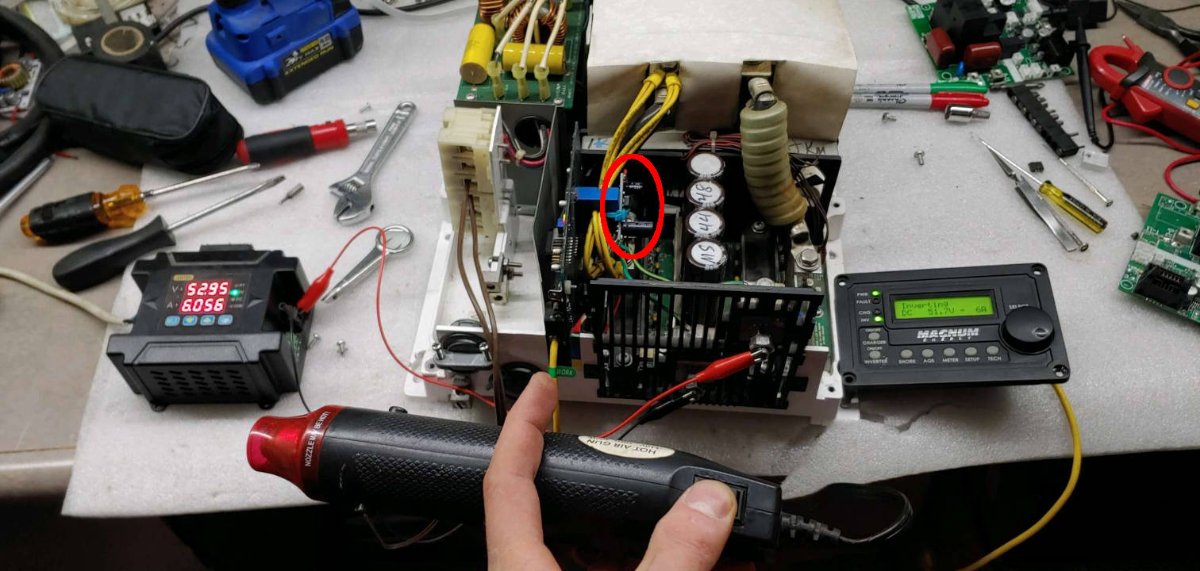
I found several things interesting:
- At least on this older model Magnum 4448, there is no way (that I saw!) to view output AC voltage or current. All you get is battery voltage--and a calculated ("assumed") battery current, as there is no battery current sensor that I could determine.
- Oh, and let's not even think about trying to use a Magnum 4448 inverter without paying for the "remote"! You literally get one button and one LED on the inverter itself--that's it! How about buying a car and finding that the steering wheel, gear shifters and dash are "extras"?
- The control board is never powered down. (Well...at least now I know it isn't, haha! But from the manual & the customer, I've kinda inferred that this is the case.) This results in a ~4.8W draw (~100mA) all the time on the batteries.
- The inverter does not have much of a soft start--but when you turn it off, it does a "soft stop" over about 2 seconds. Quite curious...and I'm not sure why!
P.S. Yes those are Genetry control boards on the right side of the photo. Can't get too distracted at my desk 😉.
Oh, and let's not even think about trying to use a Magnum 4448 inverter without paying for the "remote"! You literally get one button and one LED on the inverter itself--that's it! How about buying a car and finding that the steering wheel, gear shifters and dash are "extras"?
... A shockingly large number of consumer inverters have 1 or less controls. Most have 0. Though with the international market so common place, you get the dip switches to basically region-configure the inverter - but i don't really consider that a control as it's usually one effective configuration for each market.
GS' LCD interface is exceptional, even in upper tier inverters. Honestly, it's probably the best in the consumer market as the competition (when they even have a screen) usually has a 1 or 2 line (read; magnum, Schneider Electric) diagnostic screen and maybe some limited configuration.
Then the whole wifi interface takes it to another level. I only know of victron having a similar level of data availability - but that requires their own product suite to access it.
I think if you want to get more info click the meters button, then you can pull up AC meters and get some more information on the AC/DC voltage etc. It is pretty limited, but you do need to go a level deeper to get the meters information.
12 minutes ago, DT2 said:I think if you want to get more info click the meters button, then you can pull up AC meters and get some more information on the AC/DC voltage etc. It is pretty limited, but you do need to go a level deeper to get the meters information.
Not on this one. Meters button -> the only option for the inverter is the DC voltage and current. All of the other options have to do with external "optional addons"--which aren't present.
19 minutes ago, Sid Genetry Solar said:Not on this one. Meters button -> the only option for the inverter is the DC voltage and current. All of the other options have to do with external "optional addons"--which aren't present.
I think that one is the "RTR" or remote I guess you have to have the....Advanced router for that "ARTR" Definitely doesn't seem like the remote/router is optional.
I think that one is the "RTR" or remote I guess you have to have the....Advanced router for that "ARTR" Definitely doesn't seem like the remote/router is optional.
The only local option in "Meters" is "INV/CHG Meter" (which shows battery voltage and calculated battery current). All the rest of the options are "BM [xxx]", which I assume is "battery monitor"--and everything's blank/zero.
The comical part is that even if you buy an "advanced router"...ALL of the AC voltage/current (on BOTH the input AND output) stats are already monitored on the control board for all of the regulation and power control functionality. Magnum just apparently didn't feel that the end user would ever want to see such info.
In "Tech", the only stats found there are transformer and FET temps. That's it. Cheers!
In "Tech", the only stats found there are transformer and FET temps. That's it. Cheers!
Most important measurement is temperature to stop the inverter from catching on fire and blow up the FETs . I watch the lithium iom battery temperature always when charging with more than 6 amps . Lithium ion in ev cars are water cool and when I charge my lithium ion at 10 amps it overheat and fumes come out of the vent and I shut down the charging right now

