PLEASE NOTE: If you had an account with the previous forum, it has been ported to the new Genetry website!
You will need to reset the password to access the new forum. Click Log In → Forgot Password → enter your username or forum email address → click Email Reset Link.
The motor is 230V and the surge amps are about 10A, so the watts are ~2500W. This maybe be possible with my inverter.
I know that the pump surge is 10 amps but a 50uH 20A choke will not start a well pump because the surge may last 10 seconds and a 20A choke will not help when the battery side is drawing 100 to 150 amps . IF the surge last less than 1 second like a heat pump then it may work . The problem is that the dc voltage will drop fast and then your AC side may drop to 180VAC and the well pump will not start because the surge last 10 seconds and your AC voltage will be too low . The choke is to keep the AC voltage near 230vac but because the ASL2.0 transformer is too small to keep the voltage near 230vac for 10 seconds . I do not know of any well pump that start in 1 second unless there is no water .
The problem is that the dc voltage will drop fast and then your AC side may drop to 180VAC and the well pump will not start because the surge last 10 seconds and your AC voltage will be too low . The choke is to keep the AC voltage near 230vac but because the ASL2.0 transformer is too small to keep the voltage near 230vac for 10 seconds .
I thought the choke was to protect the mosfets from feedback from the pump motor? To address the voltage drop, which I think is the true problem, I have a 24V capacitor bank that I can connect to the dc side. I haven't fully tested that idea because I couldn't make good high-amp connections to the circuit board. I have nickel strips now and 4 gauge copper wire now, so I will try again.
I thought the choke was to protect the mosfets from feedback from the pump motor?
The choke protect the FETs from overload like a pump that do not start and also when the pump shut off . The rev 11.3 control board do not allow testing as it shut off the inverter in less than a second . The choke do not have a chance to help the pump as all power is shut down and you do not have 10 seconds to see if the FETs blowup or if the pump works . This is good but it indicate the transformer is not design properly and probably nothing to fix .
In my experience with fets they tend to instant fail from over current unlike bipolar transistors which just get hot.
That's not to say the fets aren't better, just that the safe parameters for them are much closer to catastrophe failure points than their predecessors.
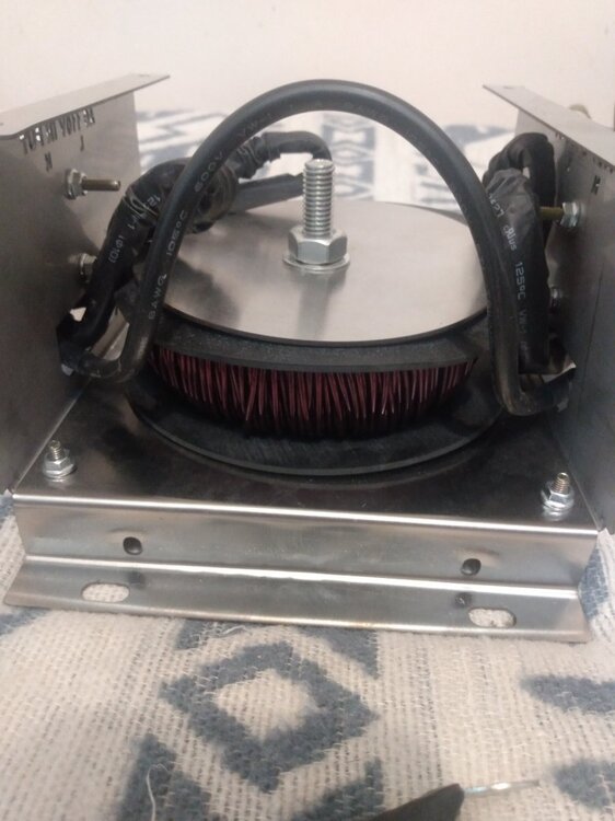
Because the slicer bridge is still a HF inverter feeding a LF transformer the choke on the primary is critical for limiting the pulse current
Because it's a bridge slicer a FET sticking on one phase will destroy the FETs on the alternate phase of the same transformer terminal as soon as energized
As far as FET drive mine has 10v drive signal with 1uS rise and 0.5uS fall times.
That seems like decent drive to me
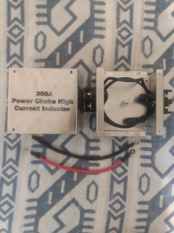
Let us know if you notice any benefits when using this choke. I am testing small aftermarket chokes on my "8000" Power Jack AMG inverter. I connected both of my small battery banks to the inverter, and started a 1/2 hp motor. I needed a small auxillary load running before the motor would run continuously.

