PLEASE NOTE: If you had an account with the previous forum, it has been ported to the new Genetry website!
You will need to reset the password to access the new forum. Click Log In → Forgot Password → enter your username or forum email address → click Email Reset Link.
Well, apparently there was an unexpected bug in the 1.2r4 (C) release...fortunately, I was able to identify the cause of the issue, fix it, and then verify that it had been fixed.
Makes a very short-cycle from 1.2r4 to 1.2r5, but I'd rather know about issues and be able to fix them, than otherwise!
Notes (in addition to the 1.2r4 notes) for 1.2r5:
- [C] Fix issue with "AC Output Shorted" error upon system startup [bug report @steve, @cali-carlos]
- resulted from a new function in 1.2r4 to half-cycle pause the regulator from increasing throttle if the current limit is hit
- Increase "AC Backfeed" threshold tolerances (due to 1.2r4 AC Output Volt measurement change)
- Fix dumb bug with "Xformer Volt" error (making it much more trigger-happy than necessary)--this issue goes WAY back!
- revert the AC Input qualification delay (prevent excessive delay with "slave" modes).
Thanks for the reports and diagnostic info 😉
Is this for A/B users? or just C users??
Is this for A/B users? or just C users??
Just Rev. C at the moment. I haven't yet gotten the changes tested on a B board.
Hmm. Regret to inform... AC Output Shorted after running in inverter mode for a few minutes. (with AC Input available)
Hmm. Regret to inform... AC Output Shorted after running in inverter mode for a few minutes. (with AC Input available)
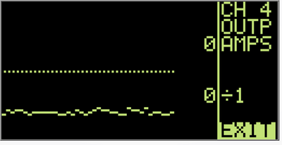
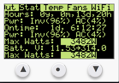
Can you provide a screenshot of the DVLT 'scope screen if the inverter faults out again with "AC Output Shorted"? Also the STAT page BtyA_Cnt and BtyAmpPk numbers? (Possible the current limit is behaving differently?)
This sounds unrelated to the previous bug reports, as the bugfix was for "AC Output Shorted" immediately upon power-up, not several minutes later.
I will grab that information if it happens again. It definitely did not happen immediately - it did it when i looked away for a moment after thinking all was fine.
I noticed that when AC input is on and charging the battery and there is no load that the display output wattage ranges from 0 to 36 watts is the max I have seen. Not really a problem, but maybe related to that short issue like the current sensor is picking up false readings.
Not really a problem, but maybe related to that short issue like the current sensor is picking up false readings.
I use a multimeter . The LCD screen show false readings sometimes .
I noticed that when AC input is on and charging the battery and there is no load that the display output wattage ranges from 0 to 36 watts is the max I have seen.
That's very interesting. Worth noting that I find myself being surprised what kind of noise sneaks around the 24-ohm bias resistors across the current sensors! But it's also worth noting that the expected readout scale for watts is beyond 1:20,000...so I'm quite pleased at how little noise there is in the readings! Curious what you read on the OUTP AMP 'scope channel when there's no output load during charge?
You're at 12v...I'm curious what kind of charge currents (on the battery!) you're running + what the charge efficiency measures out to be? (If you have the tools to measure that!) Also temps on the inverter during charge.
Not really a problem, but maybe related to that short issue like the current sensor is picking up false readings.
The "AC Output Shorted" error actually doesn't even look at current (well, apart from a code comment saying, "may want to check current"). It basically provides a zero-tolerance trip if the AC output voltage is measured under 30vAC (for 240v) for a single half-wave reading.
Up until the 1.2r4 "oops", the error has been pretty effective at staying out of the way--and one customer who was reporting persistent "AC Output Shorted" errors eventually found a loose wire on an appliance. You can guess what that wire was doing...
That's why I ask for the "DVLT" 'scope screen after an "AC Output Shorted" error--as it'll show "Measured AC Output Voltage History" for the past second or so up to the error. (That's also why the screenshot needs taken before the inverter is reset!)
Hey @dickson, if you click the "Quote" button on an existing post, it'll properly inline it in your posts! You can also drag-select text, and click the little blue "quote" button that pops out--that'll quote a specific section of the post!
That's very interesting. Worth noting that I find myself being surprised what kind of noise sneaks around the 24-ohm bias resistors across the current sensors! But it's also worth noting that the expected readout scale for watts is beyond 1:20,000...so I'm quite pleased at how little noise there is in the readings! Curious what you read on the OUTP AMP 'scope channel when there's no output load during charge?
You're at 12v...I'm curious what kind of charge currents (on the battery!) you're running + what the charge efficiency measures out to be? (If you have the tools to measure that!) Also temps on the inverter during charge.
I will test those things. One test I did is I moved the wires going through the current sensors and it does affect the reading. So will spend some time tracing them and see if improving the wire routing a bit may help with that noise.
I am curious what your battery current shunt is made of it seems to be affected quite a bit by temperature on the raw scale more than what I am used to. May need to monitor the shunt temperature to adjust it. I was taking the actual reading the the raw reading doing the math, but noticed that it changes as it gets warmer. Manganin is what I used to reduce the temperature swing issue, its just an alloy of copper. The way around that is temperature compensation, I just didn't want to get that fancy so used standard shunt that is made from manganin and modified it.
Checking the charging I am testing on the low and right now batteries are pretty full so can't crank it up yet today. 309.2 Watts input and 202.5 Watts to the battery. Ambient in the room is 75 F and I have inverter set to turn on fan at 20% at 100 it cycles on and off but never increases speed.
Hooked up to my backup battery bank that is bit lower and turned up the charging. Not as bad higher up. 808.3 Watts input and 652.7 Watts to the battery. So about 80% up higher so better. So if I end up using the charge function setting the bulk cut off is important don't want to waste that much power when its changing at lower amps.
Another test I did was checking transition from grid power to battery under load and it was not good it tried but that gap in power caused one of my AC units to lock up and shut down. So hoping if I let it sit there and drain down and try later that it will work again. Expensive so I will be careful to not let it transfer to battery without shutting down everything first.
Tested with my PowerMax not perfect comparison but turned it down to be pretty close. PowerMax Charger 880.2 in and 809.74 out about 92%. I will most likely keep the PowerMax as the primary charger when on the generator and use the GS as a backup if needed.
Got to give the inverter part some kudos though 18.4 watts idle consumption is awesome.

