PLEASE NOTE: If you had an account with the previous forum, it has been ported to the new Genetry website!
You will need to reset the password to access the new forum. Click Log In → Forgot Password → enter your username or forum email address → click Email Reset Link.
My 2 60A MSB's have the USB port so have connected gnd and next 2 pins to esp32. Not getting any response when I send the request code so really no idea what I sm doing wrong.
Can you show your connections from the ESP32 to the "USB" port, as well as the lines of code for setting up the UART & sending the request code? There might be something obvious there--again, I don't have a v118 MSB, nor do I have a MSB with a "USB" port on it, so I'm not much help with info.
Try this...
<fileStore.core_Attachment>/monthly_2022_12/image.png.a9fc9967e26522b05b364c03a8d397e5.png
I found this on Amazon... The pinout seems to match even though our connector is mini usb. So there must be some standard uart standard for USB???? (also this is upside down from our orientation)
<fileStore.core_Attachment>/monthly_2022_12/image.png.b00a68d1e45d1350d13361705ea958a6.png
Now mine is a 40A version but I don't imagine they would change the pinout for the 60A.
Also not I have not tried the USB port. I was dumb enough to solder headers to where the Wifi module would go.
And I'm only 90% sure of the RX/TX (there is a small chance I swapped them)
When I did this, I didn't know the usb was connected to the uart! It would be cleaner to hack a USB cable! Maybe I'll redo this someday to use the cable..
Jim
So there must be some standard uart standard for USB????
Not really...but the USB standard is +5v, D+, D-, GND. (Mini USB adds a 5th lead for whatever reason.)
So the middle 2 leads would be the easiest RX/TX option for UART usage.
@busky Can you verify the USB "RX/TX" leads go to the same pins as the WiFi connector?
Not really...but the USB standard is +5v, D+, D-, GND. (Mini USB adds a 5th lead for whatever reason.)
I didn't think so either.. But that picture was from an Amazon cable.. So someone else is using it for uart as well
QuoteSo the middle 2 leads would be the easiest RX/TX option for UART usage.
@busky Can you verify the USB "RX/TX" leads go to the same pins as the WiFi connector?
The absolutely do. I ohmed them out. I was not just sure 100% that I didn't mess up the RX/TX and swap them. But I'm 95% sure I have the RX/TX correctly labeled
Jim
https://www.amazon.com/Micro-1-64ft-Female-Tablet-Extension/dp/B08JJ1B95P
I've never seen uart signals on a usb cable.. But it matches what MSB used....
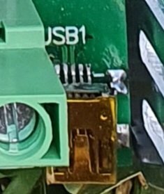
Here is my usb connector. I measured left most pin as gnd and then using next 2 pins for rx/tx.
I would suspect (concurring with @busky) that the RIGHTMOST pin is likely ground. Note that it is connected to a large copper pour (often known as the "ground plane"). Leftmost pin is likely positive (+3.3 or +5.0, depending).
If you measure the 2 "RX/TX" leads separately with a meter, you should find voltage (+3.3v/5.0) on one of them, with respect to battery negative (which SHOULD be the rightmost lead).
Thanks. Will double check but can't do till tomorrow.
So on the USB connector, I'd suggest a DMM in "DC milliamp" scale, and try shorting the suspected RX/TX leads to ground one at a time. (Try to avoid shorting the leftmost pin, that's likely the 5v rail.)
You should get something like 15-20mA from one pin, and <1mA off the other one.
-> the 15-20mA is TX (output)
-> the <1mA is RX (input)
No idea what I have done differently as I have swapped the pins over and over again.
If you were using the leftmost USB pin as "ground", that would have referencing the TX/RX signals on the "USB port" from the wrong voltage potential. (Technically, the serial signals as seen from the MakeSkyBlue MCU would have been 0 = 5v, 1 = 10v--quite beyond the 0-5v range of the MCU on the board.)
but that it works this way proves your code is good 😉👍
my guess about the ground referencing issue was from this post:
Here is my usb connector. I measured left most pin as gnd and then using next 2 pins for rx/tx.
but it appears that the rightmost pin on the "USB" connector is ground.
and now that it's working, your comment:
Only difference is gnd connected to the top left pin on the board and not thru usb.
...as long as you have the correct grounding potential to the MCU, it should work.
Glad to hear that comm is working on a MakeSkyBlue v118 with "USB" port.
Thanks for assistance. When looking at the top photo of the usb I was using right most pin as gnd. As far as I measured this was gnd. At least it's responding so I can sort out connections properly. I also have a v118 40A msb without usb so will have to look at that in the coming weeks.


