PLEASE NOTE: If you had an account with the previous forum, it has been ported to the new Genetry website!
You will need to reset the password to access the new forum. Click Log In → Forgot Password → enter your username or forum email address → click Email Reset Link.
.sounds like your "MPPT" algorithm needs some serious adjustment ??
changinging the TOP value from 149 to 75 exactly doubled the pwm freq generator on my dso..
Without digging into your code / architecture, it appears that you're using some fairly base-level MCU controls (which is great...but may have some unexpected caveats). At least in my experience, the normal "timebase" with a timer (especially when using a "top" variable) will also limit the maximum number you can use for PWM control.
For example, in a Microchip PIC, setting the PRx register on a hardware timer is basically what you're doing here. But the maximum PWM pulse width is determined by the PRx register--i.e. if PRx == 159, then 100% PWM duty is also at 159 (even though the register can go up to 255).
Again, without digging into the code & architecture, etc. that's just an FYI. My thoughts would be to leave "TOP" at 149, and change the prescaler from 16 to 8...as then you'd have a tiny bit more resolution.
...but it really won't make that much difference for actual functionality on the PWM output.
What kind of DSO do you have? It would be pretty easy to see if the PWM frequency is too high/too low by checking input ripple. If the inductor is saturating (i.e. frequency too low), you should be able to see that with sharp ripple on the solar input.
its just a low bandwidth nothing dso kit thing..I may have to borrow a real scope from a local friend..U have me wondering that maybe I can get this project 'fine-tuned' !! that would be cool..
I will check with a friend today..one thing I noticed--the heat didnt come back.. so that has me wondering also.. it was quite noticable before when I went from 40khz to 20khz.. now having gone back, it should have returned but doesnt seem to have..there must have been more factors involved..
I was able to locate the div16 in two places and changed that to div8, went back to the original 159 TOP and the stupid thing compiled!!!!
got it running on both msbs now for today.. many thanks!!
I will check with a friend today..one thing I noticed--the heat didnt come back.. so that has me wondering also.. it was quite noticable before when I went from 40khz to 20khz.. now having gone back, it should have returned but doesnt seem to have..there must have been more factors involved..
Unless you have a meter to measure frequency, it's possible that the frequency was considerably higher (not what you expected)--which if the freq. is too high, switching losses in the FETs will start to become problematic.
With a 'scope, you would be able to determine exactly what's going on, though. Here's a graph I found online showing the difference between ideal switching amperage conditions vs saturated inductor amperage waveforms:
<img align="left" alt="How to Understand Power Inductors Parameters for DC/DC Converters" border="0" data-ratio="89.60" height="224" hspace="10" width="250" data-src=" 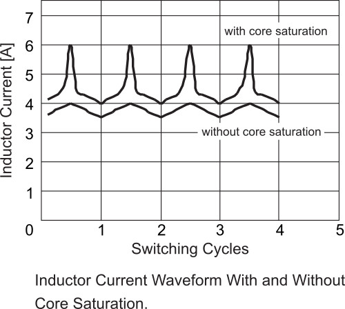 " src="/applications/core/interface/js/spacer.png">
Notice that when the inductor saturates, it basically "shorts out"--which will drag your panel voltage down to battery voltage with no conversion. If the core is saturating, the switching frequency needs increased in order to reduce the pulse width.
However, I'm suspecting that switching frequency may not be a "one size fits all"--the switching frequency MAY need dynamically adjusted based on the input/output voltage drop, etc., etc. Just a guess, not something I've tested though.
Unless you have a meter to measure frequency, it's possible that the frequency was considerably higher (not what you expected)--which if the freq. is too high, switching losses in the FETs will start to become problematic.
I made a simple feedback loop-- headroom vs pwm freq..I assumed higher pwm freq would be needed to avoid saturation and therefore loss of headroom..headroom defined as PVv-BATTv
if(mpptloopTMR==0){WATTS=scanVitals();
freq=f37KHZ;
int16_t headroom=PVv-BATTv;
if(headroom<10)freq=f40KHZ;
if(headroom<5)freq=f42KHZ;
if(headroom<3)freq=f48KHZ;
if(headroom<2)freq=f52KHZ;}
I modified the analogWriteKHZ function to include freq control..I now pass a int as TOP to the function..got alot of sunlight today to test this..I really need to build up some sort of data logging to make better sense of the results..
I made a simple feedback loop-- headroom vs pwm freq..I assumed higher pwm freq would be needed to avoid saturation and therefore loss of headroom..headroom defined as PVv-BATTv
This is my guess...but I have not tested this out, nor do I have much experience with switching converters (usually just follow the manufacturer datasheet!)
You would need an oscilloscope to figure out exactly what's going on. Not sure if a little tiny DSO kit will have sufficient resolution--but being well below 1MHz, they might.
This is my guess...but I have not tested this out, nor do I have much experience with switching converters (usually just follow the manufacturer datasheet!)
I think u might be correct hunch.. I just am investigating..I want to maximize my mppt routine efficiency if possible..thought I would look at variable pwm freq vs. headroom for today..thanks--
still dont have a working setup whereI can scope the charging ripple..just looking at numbers..
on the subject of inverters-- Don Lancaster did someinteresting work-- magic sinewaves..brilliant stuff.. maybe u are already aware of his work..interesting reading..
https://www.tinaja.com/glib/msintro1.pdf
on the subject of inverters-- Don Lancaster did someinteresting work-- magic sinewaves..brilliant stuff.. maybe u are already aware of his work..interesting reading..
It is quite interesting reading, for sure.
Don't think we'll use it at Genetry Solar....largely because there's licensing/royalties required for use. 5% of sales adds up really fast.....if we made that much actual profit on each inverter sold, we'd be a lot farther ahead than we are...
I have a very hard time believing that the output waveform will be very clean. 15 pulses across an entire waveform...yeah, you might be able to get the harmonics super clean through use of the very careful mathematics. But I can just about guarantee you that the actual waveform will more resemble a Lego sculpture than a beautiful sinusoid 😉. Those large transformers don't "filter" much of anything...not unless there is some hugely significant hardware filtration before the main transformer.
Perhaps quite interestingly, I did not see any hardware examples for this "magic sinewave"--nor any real output sine screenshots. Nothing but hypothetical mathematical calculations. (To be fair, I glanced through about 5 of the PDFs, not all of them.)
Still quite an interesting concept, though.
he's a MPLAB guy like u, apparently--
Firmware Considerations While low end applications pretty much demand a PIC or similar microprocessor, use of wider bus devices or even DSP digital signal processing techniques may prove of advantage for higher end development. Because of the exacting requirements of Magic Sinewaves, some ultra precise and non-mainstream programming techniques will usually prove of value. Timing and precision requirements can often end up unusually strict.
https://www.tinaja.com/glib/msinexec.pdf
u might strike a private deal and have a win-win.. glad u enjoyed..I think he's associated with ASU
he's a MPLAB guy like u, apparently--
I'm so tired of MPLAB X, better known on the Microchip forums as "Buglab X". A very frustrating program, to say the least. (MPLAB IDE, the non-Java-based version before MPLAB X, was a lot better.)
The only reason I stick with Microchip PICs are...well...they're easiest to procure from China due to popularity (as the U.S. has zero stocks). Oh, and Microchip's fabs are in the States too..."buy American if you can."
their [only] foundry used to be in Chandler,az.. I suppose they farmed out to backup fabs in the far east.. everybody doing that..
I might have some coolinfo at the end of today.. ur hunch about adj the pwm freq may or may not prove out..today.. I have to wait for the big solar this afternoon to be able to compare to yesterday..
it alsmost looks like u are right but with a conditional.. to my surprise, it[the analogWriteKHZ()] wants to use HIGHER pwm freq to maintain a headroom.. I originally wrote it up in the opposite..had to turn that around..
but now it is a show-down between two outcomes..
1-- yes u are correct, however due tothe small size of the torroids, true mppt gets 'limited to a certain limited level..
2 ignoring true mppt, more 'juice' is made available to the output by just ignoring mppt over a certain current level and just flying pwm to harvest more amps..
I have pushed the pwm gerator up to 60khz now at top end.. and efficiency is good at 60khz ..
but at limited current..
should know which is the case by end of solar run..
if(mpptloopTMR==0){WATTS=scanVitals();
freq=f37KHZ;
int16_t headroom=PVv-BATTv;
/*
if(headroom<200)freq=f38KHZ;
if(headroom<100)freq=f40KHZ;
if(headroom<50)freq=f42KHZ;
if(headroom<30)freq=f48KHZ;
if(headroom<20)freq=f52KHZ;}
*/
if(headroom<200)freq=f60KHZ;
if(headroom<150)freq=f52KHZ;
if(headroom<100)freq=f48KHZ;
if(headroom<50)freq=f42KHZ;
if(headroom<30)freq=f40KHZ;
if(headroom<20)freq=f38KHZ;}
NOTE: 200=20.0v I am avoiding float math..just need .1v resolution..
NOTE: 200=20.0v I am avoiding float math..just need .1v resolution..
That's a mark of someone who truly knows embedded systems. Two thumbs up from me 👍👍
their [only] foundry used to be in Chandler,az.. I suppose they farmed out to backup fabs in the far east.. everybody doing that..
Not according to Wikipedia--or Microchip's own website--but it wouldn't surprise me to hear that they had. Just can't find any corroborating evidence to say that they have...
1-- yes u are correct, however due tothe small size of the torroids, true mppt gets 'limited to a certain limited level..
I would be quite curious to see if the toroids are saturating; if they are, that'd explain a lot 😉. Just not curious enough to tear an MSB apart and measure the toroids myself, as I do have access to a (very old) L-C meter...
2 ignoring true mppt, more 'juice' is made available to the output by just ignoring mppt over a certain current level and just flying pwm to harvest more amps..
So technically, "MPPT" algorithms are an attempt to solve for "unknowns"--namely, the following:
- panel VOC (open circuit voltage)
- temperature coefficient (as this is SIGNIFICANT!)
From a very basic perspective, the very minimum that your MPPT routine would need to do would be to regulate solar panel voltage (at least until battery voltage setpoints are reached)--and prevent it from getting pulled down too far.
If you knew the panel temp and maximum-power-point spec, you could technically hardcode said values into the MPPT. And in that vein, it's possible that you could even have the user just input the following specs:
- panel open-circuit voltage
- maximum power point voltage
- panel temperature coefficient
...and have the MPPT calculate panel temperature from open-circuit voltage and temp coefficient. Then scale the max-power-point voltage by the determined temp--and bingo, no more "MPPT searching" required (except for periodic open-circuit voltage checks--as panel temps will change quite a bit over a day).
You can reference this graph for comparison:
<img alt="PV Panel output voltage - shadow effect? - Victron Energy" data-ratio="75.08" style="width:230.203px;height:172px;margin:0px;" width="999" data-src=" 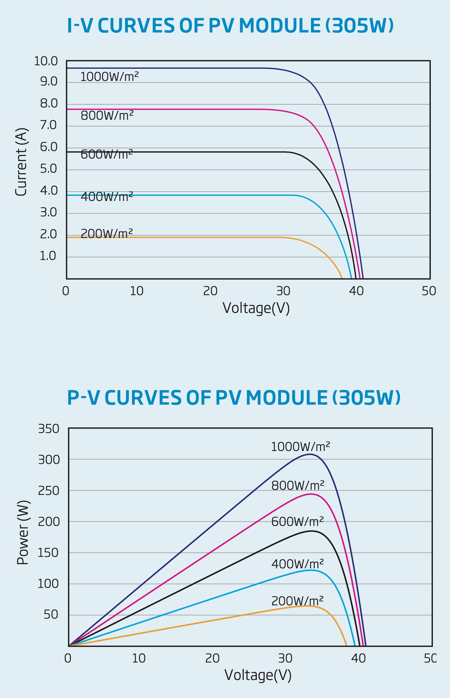 " src="/applications/core/interface/js/spacer.png">
Note in the top graph that the maximum power point voltage is ~31-35v regardless of the available light. The only reason you wouldn't want to simply hardcode the panel "maximum power point" voltage is because the temperature coefficients are no laughing matter on solar panels--a sizeable array will easily move the power point by 10-20v based on temps (lower voltage at higher temps, higher voltage in low temps).
But if you know the "25C open circuit voltage", and the temperature coefficient...you can calculate the panel temp by shutting the MPPT off, measuring open-circuit voltage, and then determine the necessary temp coefficient to reach the measured open-circuit voltage (vs configured open circuit voltage). Then scale the "maximum power point voltage" by the now-known temp (based on the temp coefficient) -> now you know exactly what panel voltage to regulate. No guessing required!
Also from the top graph, you will note that the amperage does not change from short circuit all the way up to max-power-point. This is why holding an excessively low panel voltage is so detrimental to actual output power--you literally cut the output power in half for nothing!
That's my 2 cents of ideas...from someone who isn't exactly planning to reinvent the wheel with a Genetry MPPT anytime soon 😉.
Thanks--I appreciate the two thumbs up and all ur thoughts on best ways to get 'er dun..mppt..
yeah I avoid float math like a plague..even at 48mhz, it hurts..I hope u are not stuck at 20mhz pic..that used to be their 'fast' stuff..float at 20mhz would be a deal-killer..
mppt --IMO--is more of a living thing than just a simple code function..the web is loaded with stupid mppt.. I suppose anyone with 'good stuff keeps it to themselves..fair enuff.. however, Iam retired,really dont care so much about making the $$, and I have a passion to unlock this stupid little msb and make it sing..dont want to change out parts, cut traces, add or remove anything.. just pound code and make it do the best job IT is possible of..
today was an exercise in futility.. weather was identical to yesterday till just after the major lobe of solar was coming in on the one solar panel string I was waiting for..THEN CLOUDY.. so just added too my already confusion..not good data..except to observe a slightly reduced harvest after adding my selectable pwm freqs.. I need to pound better code to allow for more factors before I select a pwm freq..
About ur ideas.. ur idea to compute rapidly the best point to mppt at by the graph and user input-- all good-- however, consider this..
1-- people buying msb most likely are NOT all that literate concerning the specs u would want them to punch in in a setup dialog.. easy for u or maybe me,but probably asking toooo much in general for the general buyer of msb..
2--GOTCHA!!... partial shading is a mother.. in reality, a simple one panel graph with perfect insolarification is not what is out there in reality..
here is just one article about partial shading..there are more..
https://ieeexplore.ieee.org/document/8507897
thats what brought me to just doing a quick scan to actually see whats out there at the moment..
my scan routine takes about 3 or 4 sec..but I havent trimmed it out yet.. might get it down to half that.. fortunately the filter caps in msb are minimum values..like 68uf..so that actually works to my benefit for a quicker scan.. then I get the real data--including MULTIPLE peaks..which are common..so my logic presently is to do rapid scans not so often but maybe one every 4 or 5 or 10 minutes,just to make sure I get back to the best peak if I get lost somehow.. a couple secs every 5 min--not that bad time lost..plus u get 'some' charging during the scan..
throw cloudy up/dn rapid loss/gain and mppt becomes more like a duck-and-roll shoot-out than a picnic..my data for today is basically meaningless..just throwing it in for amusement value..hot day here today and I did notice that higher pwm freqs appeared to boost efficiency but at the same time produced an increase in temperature rise..probably mostly from inducrors?? starting to think temp coefiicient of the inductors is also a major factor to deal with..another thermal run-away situation..boost the pwm freq and under heavy current-- these too-small-inductors become heating elements primarily..
I think my final design will be to run mppt with multiple pwm freqs ONLY up to a specific BATTi current then admit the torroids are saturated and just use minimum pwm freq and basically run pwm.. thats where I am headed..
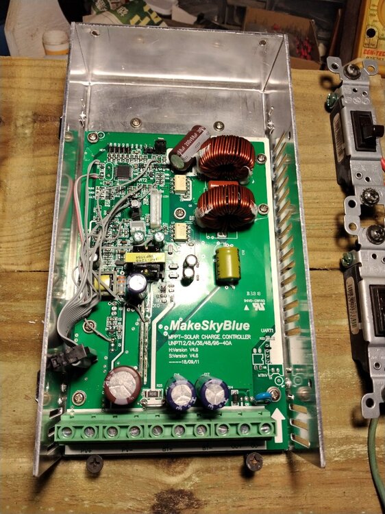
look at how tiny these inductors are in the 30A msb..thats the ones I am using to test with..not the 60A msb..
I appreciate ur time--
look at how tiny these inductors are in the 30A msb..thats the ones I am using to test with..not the 60A msb.
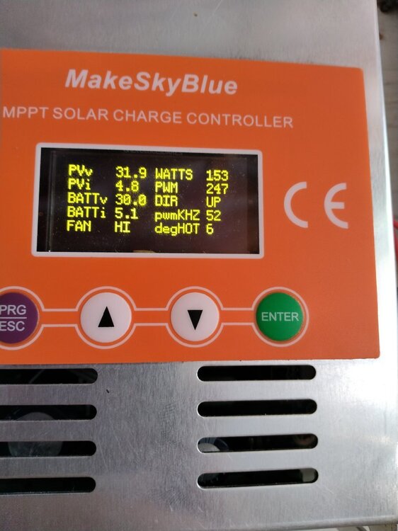
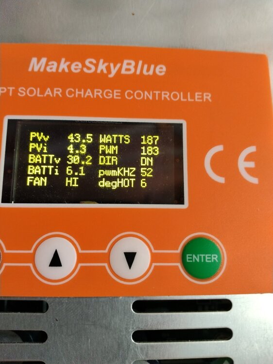
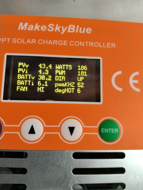
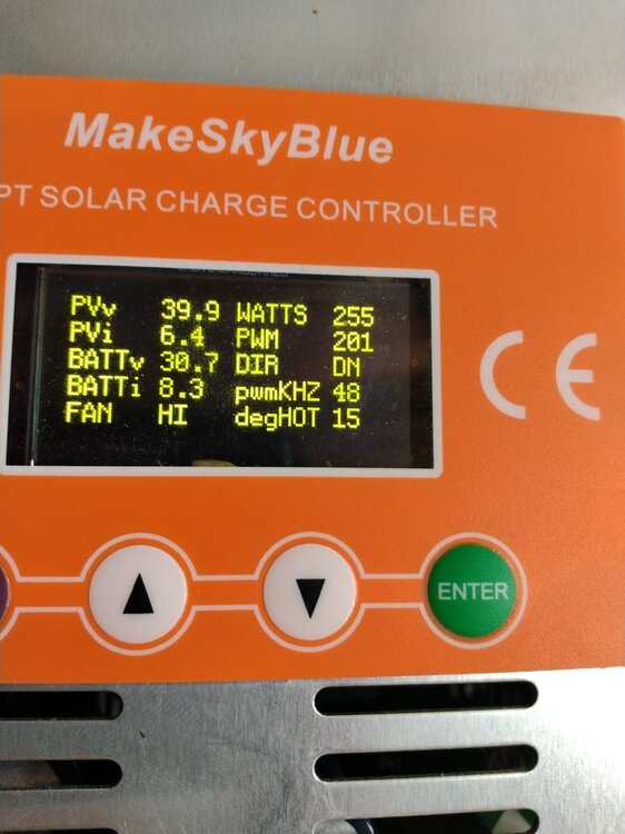
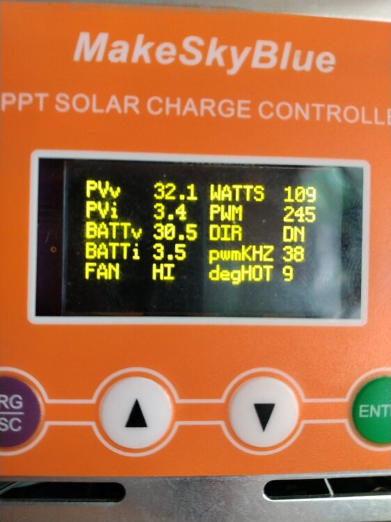
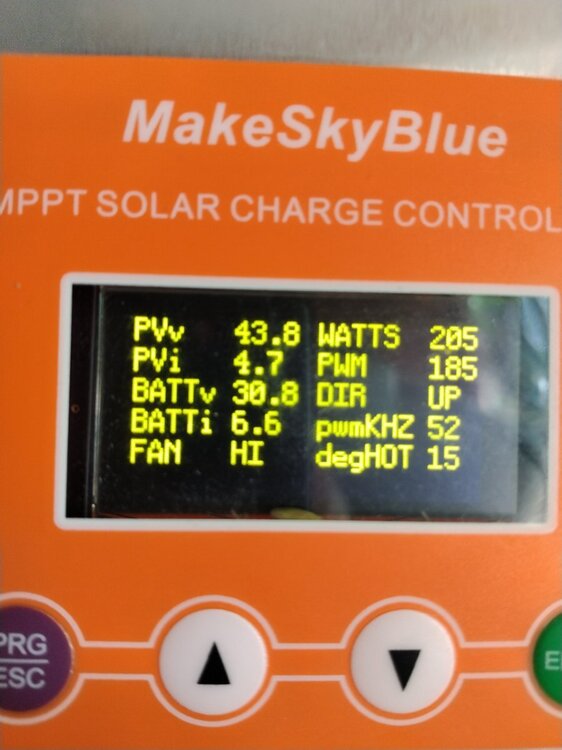
pwmKHZ 48 give the best reading 255 watts
