PLEASE NOTE: If you had an account with the previous forum, it has been ported to the new Genetry website!
You will need to reset the password to access the new forum. Click Log In → Forgot Password → enter your username or forum email address → click Email Reset Link.
Yes I am the same Back Shed Warpspeed.
I can run it at any frequency, its just a simple pwm controller chip with the usual RC ramp generator. But its currently set to run at around 20Khz nominal.
You are right, a higher inductance solves the core loss problem and an unusually low ac ripple current solves the skin effect problem too.
I don't see dc voltage drop across the choke being a serious issue at higher dc voltages, its more of a temperature rise problem at full flat out current.
Everything changes significantly at low voltage, and much higher current. But commercial dimmer chokes look like a good option for 96 volts and above. This is a company in the UK that makes a good range, but I expect they would be rather expensive. China may be a more happy hunting ground. I have a selection of dimmer chokes here that I have had for years, and they work very well, so I don't need to buy more right now myself.
[URL] https://carnhill.co.uk/products/dimmer-chokes-to-80a/ [/URL]
I don't see dc voltage drop across the choke being a serious issue at higher dc voltages, its more of a temperature rise problem at full flat out current.
well...the 2 have a direct correlation, so that's why I mentioned it. The higher the DC resistance, the higher the guaranteed losses are 🤣. Switching losses obviously being a separate category.
It's relatively interesting that I can account for a large percentage of inverter transformer losses simply by measuring the DC resistance of the coils and calculating (via Ohm's Law) losses at a certain load.
still need to create a video on a very easy way I've found to determine the ideal turns/volt of an unknown core for low-frequency inverter usage...
still need to create a video on a very easy way I've found to determine the ideal turns/volt of an unknown core for low-frequency inverter usage...
Yes, its not too difficult. Faraday's law and one of the online flux calculators do all the work for you. There are very worthwhile gains to be had in reduced idling power by reducing flux density, which is definitely the way to go for an inverter transformer. Then, as you say, the ohmic resistance of the windings can be measured easily enough.
Chokes are a much more complicated beast to design. There are two quite different aspects of design that need to be looked at separately. The dc part of it which is current density in the wire and the resulting temperature rise, the measured inductance, and flux density due to dc magnetisation.
Then there is the ac part of the design, which is flux swing and core loss, and the resulting temperature rise due to core heating, also skin effect in the wire, and maybe self resonance at some inconvenient frequency.
And of course core saturation due to the combined dc and ac flux. Transformers are much easier !!
Dimmer chokes are a pretty obscure choke application, but they are designed to work with high ac voltages across the winding which makes them an interesting candidate for higher voltage solar controllers.
Chokes for low voltage switching power supplies, or noise reduction chokes, will probably fry the core if you try running them with hundreds of volts across the winding, which is what we will be doing in a high voltage solar controller.
Yes, its not too difficult. Faraday's law and one of the online flux calculators do all the work for you. There are very worthwhile gains to be had in reduced idling power by reducing flux density, which is definitely the way to go for an inverter transformer.
Umm...how about neither Faraday's Law or an online calculator? A way where you don't have to be an algebra whiz (or even know algebra)...a way in which you don't have to do a single bit of guesswork as to what the core might have been made out of--nor do you have to know the dimensions of the actual core.
All you need is a variac, AC voltmeter, and an AC ammeter...and an "unknown" transformer with a winding on it (one can easily be put on it for testing purposes).
In short, if you "sweep" the voltage range, taking samples every few variac volts (depending on the number of turns in the coil...I tend to sweep at 20v/reading if it's a 120v coil) and write down the measured current. (It may help to put one lead of the AC voltmeter through the core & short the 2 ends together, a simple "one turn meter"). Once the current starts to skyrocket, you know you've gone high enough with the voltage.
Then simply sit down and go through the table, divide the voltage of each "sample" by the current measured at that voltage. The most amazing thing pops out: you should get a VERY clear "bell curve" peaking at the "ideal" turns/volt number (you'll probably want to crucify me for dubbing it the "core voltage", haha!)
FWIW I did this test on a huge E-core transformer from a 3-phase industrial battery charger...and the "divided result" remained about as flat as a board as far as I went, with no "peak" in sight. Conversely, all the toroids I've tested had a very clear "bell".
Here's a "sweep" of a PJ ASL5 core that I did:
| volts | amps | delta | |
| 20.4 | 0.016 | 1275 | |
| 40.2 | 0.028 | 1435 | |
| 60.25 | 0.037 | 1628 | |
| 80.4 | 0.047 | 1710 | peak |
| 100.4 | 0.059 | 1701 | |
| 120.1 | 0.073 | 1645 | |
| 140.1 | 0.1 | 1401 | |
| 160.3 | 0.181 | 885 | |
| 180.4 | 0.766 | 235 |
(note that "volts" was at the variac, not the turns/volt "core voltage" reading...which is a lot more valuable. In this case, there were 120 turns of wire, so a very simple division of the "volts" by 120 gives the "core voltage" which a transformer winding formula can directly be based off of.)
Also note that in this case, the transformer spec was for 1v/turn--which from the sweep results is notably on the higher side of the "peak."
As far as reduced flux density...there's definitely a place for that. I will note that in larger transformers, it sometimes is significantly beneficial to actually PUSH the flux density slightly as a worthwhile tradeoff for significantly reduced wire losses. Obviously, if the goal is lowest idle current, a lower flux density is a very handy trick--but it will result in notably increased wire losses due to the increased wire length, and the reduced number of parallel strands possible.
I have yet to get into chokes/high frequency transformers, etc., etc.
That is both very odd and very clever !!!
I have never seen it done that way before for 50/60Hz transformers, but I can see how it works. As you increase the ac excitation (with your variac) the flux swing increases. Now the magnetisation curve for most materials is an S shape. The curve starts out shallow near zero, the slope increases with increased excitation, then starts to flatten out up near saturation.
The inductance of the winding changes as you crank up the ac voltage (the dynamic permeability changes) and that also changes the measured magnetising current. At some specific excitation voltage the inductive reactance peaks and relative current dips.
How much it peaks, depends a lot on the initial permeability and how lossy the material is. I can well imagine that a good tape wound grain oriented steel toroid will peak a lot higher than a crappy old iron E and I lamination transformer.
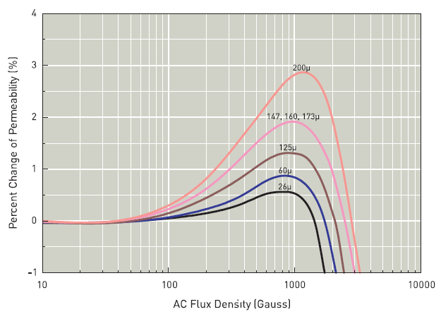
Here are some curves for various types of powdered iron toroid (not steel) and you can clearly see the effect of ac flux density on the percentage rise in permeability. The figures are nothing like that for steel, but the overall shape is classic.
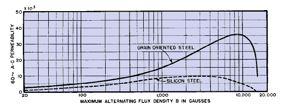
I did eventually track down a curve of flux density versus permeability for grain oriented silicon steel that our beloved inverter toroids are made from. It seems that the peak of your bell curve tops out at about 9,000 Gauss or 0.9 Teslas in metric.
[URL] http://www.vias.org/eltransformers/lee_electronic_transformers_03_03.html [/URL]
If you have read any of my transformer design threads on The Back Shed, you will already know my own recommendation for designing an inverter transformer for low idling current is to design for one Tesla flux density, and four amps per mm square current density in the wire. Not too far from the figure you recommend from your own testing.
Most commercial toroidal transformers are designed to run at 1.5 to 1.7 Teslas which is way too high for us. Idling current will be very high, and there will be a horrific current surge at initial power up. So we have both arrived at a very similar figure by very different means.
6 hours ago, Warpspeed said:I did eventually track down a curve of flux density versus permeability for grain oriented silicon steel that our beloved inverter toroids are made from. It seems that the peak of your bell curve tops out at about 9,000 Gauss or 0.9 Teslas in metric.
[URL] http://www.vias.org/eltransformers/lee_electronic_transformers_03_03.html [/URL]
If you have read any of my transformer design threads on The Back Shed, you will already know my own recommendation for designing an inverter transformer for low idling current is to design for one Tesla flux density, and four amps per mm square current density in the wire. Not too far from the figure you recommend from your own testing.
Most commercial toroidal transformers are designed to run at 1.5 to 1.7 Teslas which is way too high for us. Idling current will be very high, and there will be a horrific current surge at initial power up. So we have both arrived at a very similar figure by very different means.
//content.invisioncic.com/g308908/monthly_2022_09/lee_electronic_transformers-70a.gif.9e742ca8a5602b7b8c6ca837b35d32e1.gif
So I prefer to keep the terminology hillbilly simple...and call it "core voltage" (though I am aware the core is a magnetic carrier, not an electrical carrier)...and said "core voltage" is directly dependent on the size of the core. A small core may run 0.8v ideal....and the 12kw GS special-order cores are pushed to 1.85v ("ideal voltage" of 1.5v). Makes a huge difference in the amount of wire required.
The smaller core wound for 1.0v "core voltage" will happily trip a 15A thermal circuit breaker (power strip) if you just flip a 120v AC line power switch on to the transformer--so yes, I'm quite aware that toroid inrush current is a real thing.
Yup.
Nothing at all wrong with keeping it simple.
Thinking about this all a bit more, the published curve in my previous post uses a logarithmic scale for flux density. They always do it that way, but it stretches out the low end, and compresses the high end of the curve. If it were drawn with a linear scale for flux (and applied ac voltage) the curve would look a lot more like the bell curve you spoke of previously.
Another thought, is that the grain oriented silicon steel alloy is going to be slightly different from each supplier and the heat treatment may vary a lot too. So not all toroids are going to peak at exactly the same flux density, or show the same peak.
Actual measured magnetising current, and inverter idling power can vary quite a lot from toroid to toroid. but about 20 to 30 watts for a 5Kw transformer seems to be achievable. Back in the early days, the first Oz inverters were using toroids running at much higher commercial flux densities of 1.5 + Teslas, and idling power was more like 90 to 120 watts for a 5Kw transformer. The whole thing has come a very long way over the years.
Your test method finds the actual peak, and that has to be better, especially with recycled cores of dubious origin. With brand new cores, the published data can definitely be relied upon, and is how I have always done it in the past.
Actual measured magnetising current, and inverter idling power can vary quite a lot from toroid to toroid. but about 20 to 30 watts for a 5Kw transformer seems to be achievable .
MY PJ ASL9.0 transformer has low idling power . The EG8010 like in the Oz Inverter works with the ASL9.0 PJ transformer and low idle current .
With brand new cores, the published data can definitely be relied upon, and is how I have always done it in the past.
Of course it's often easier to spec things from a datasheet--especially if the work is being done overseas. Getting datasheets can be rather difficult sometimes...to say nothing of trying to convert the radixes they used to something that makes sense.
...but it's also nice to have a way to determine the spec of an unknown core.
...but it's also nice to have a way to determine the spec of an unknown core.
Have to agree.
BIG PROBLEM, lipo4 BMS shut down due to a imbalance and blew out (probably) the MOSFETs.
Does anyone know where I can get them?
is there a way to work around this.
In the meantime, I think I'll leave a old lead acid bank parallel to the lifpo4(which I hate to do) so the controller doesn't get surged from excessive VOC.
BIG PROBLEM, lipo4 BMS shut down due to a imbalance and blew out (probably) the MOSFETs.
sorry, I must have missed this post in my recents.....
Depends on the part number on the FETs (which I don't have off the top of my head).
Domestic sources would include Mouser and Digi-Key; the best Chinese source (for Chinese parts!) I've found is LCSC.com
It's also worth checking to see if the rest of the unit still powers up even with blown FETs. It's possible the high overvoltage caused a total unit failure.
And it is always worth noting that failure can often travel upstream from the FETs themselves, to the driver ICs. In other words, even if "just the FETs seem to be blown", it's possible that invisible damage has been sustained by the FET drivers--which can cause replacement FETs to blow as well.


